Service Manual
Page 1
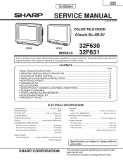
... INSTRUCTIONS 6 » SERVICE ADJUSTMENT ...10 » CHASSIS LAYOUT ...13 » BLOCK DIAGRAM ...15 » DESCRIPTION OF SCHEMATIC DIAGRAMS & WAVEFORMS 17 » SCHEMATIC DIAGRAMS ...18 » PRINTED WIRING BOARD ASSEMBLIES 34 » REPLACEMENT PARTS LIST ...39 » PACKING OF THE SET ...49... Channel Plan U.S.A.) Specifications are subject to be used for after sales service only. SHARP CORPORATION This document has been published to change without notice. GB-3U 32F630 32F630 32F631 MODELS 32F631 In the interests of user-safety (Required by safety regulations in some...
... INSTRUCTIONS 6 » SERVICE ADJUSTMENT ...10 » CHASSIS LAYOUT ...13 » BLOCK DIAGRAM ...15 » DESCRIPTION OF SCHEMATIC DIAGRAMS & WAVEFORMS 17 » SCHEMATIC DIAGRAMS ...18 » PRINTED WIRING BOARD ASSEMBLIES 34 » REPLACEMENT PARTS LIST ...39 » PACKING OF THE SET ...49... Channel Plan U.S.A.) Specifications are subject to be used for after sales service only. SHARP CORPORATION This document has been published to change without notice. GB-3U 32F630 32F630 32F631 MODELS 32F631 In the interests of user-safety (Required by safety regulations in some...
Service Manual
Page 18
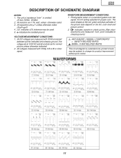
... on a standard gated color bar signal, the tint setting adjusted for product improvement without prior notice. This circuit diagram is omitted. (K=kΩ=1000Ω, M=MΩ) 2. 32F630 32F631 DESCRIPTION OF SCHEMATIC DIAGRAM NOTES: 1.
... on a standard gated color bar signal, the tint setting adjusted for product improvement without prior notice. This circuit diagram is omitted. (K=kΩ=1000Ω, M=MΩ) 2. 32F630 32F631 DESCRIPTION OF SCHEMATIC DIAGRAM NOTES: 1.
Service Manual
Page 33
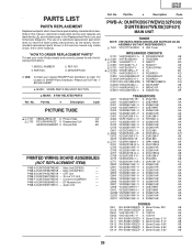
...same safety characteristic as the factory recommended replacement parts shown in the Replacement Parts Lists and Schematic Diagrams. The use of SHARP Parts Distributor, Please call Toll-Free; 1800-BE-SHARP 5 MARK: SPARE PARTS-DELIVERY SECTION ' MARK: X-RAY RELATED PARTS Ref. PWB-A...the following informations. 1. No. electrical components having such features are identified by å and shaded areas in this manual ; Main Unit(32F630) - PWB-F DUNTKB207WEA5 - Audio Unit - Part No. 5 Description Code PICTURE TUBE ' å V101 VB80AJZ90X+3E X Picture Tube ...
...same safety characteristic as the factory recommended replacement parts shown in the Replacement Parts Lists and Schematic Diagrams. The use of SHARP Parts Distributor, Please call Toll-Free; 1800-BE-SHARP 5 MARK: SPARE PARTS-DELIVERY SECTION ' MARK: X-RAY RELATED PARTS Ref. PWB-A...the following informations. 1. No. electrical components having such features are identified by å and shaded areas in this manual ; Main Unit(32F630) - PWB-F DUNTKB207WEA5 - Audio Unit - Part No. 5 Description Code PICTURE TUBE ' å V101 VB80AJZ90X+3E X Picture Tube ...