
Instructions for Use
Page 52
Active TransmittAerCCo3m2b0in0er 8:1 Instruction manual
Active TransmittAerCCo3m2b0in0er 8:1 Instruction manual
Instructions for Use
Page 53
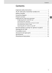
Contents Contents Important safety instructions 2 The AC 3200 active transmitter combiner 8:1 5 Delivery includes 5 Connection diagram 6 Product overview 7 Putting the AC 3200 into operation 8 Preparing the AC 3200 for use 8 Connecting the antenna 10 Connecting a transmitter to the AC 3200 10 Connecting the mains cable 11 Switching the AC 3200 on and off 11 Recommendations and tips for optimum reception 12 Cleaning the AC 3200 12 If a problem occurs 13 Accessories and spare parts 14 Specifications 15 Manufacturer Declarations 16 1
Contents Contents Important safety instructions 2 The AC 3200 active transmitter combiner 8:1 5 Delivery includes 5 Connection diagram 6 Product overview 7 Putting the AC 3200 into operation 8 Preparing the AC 3200 for use 8 Connecting the antenna 10 Connecting a transmitter to the AC 3200 10 Connecting the mains cable 11 Switching the AC 3200 on and off 11 Recommendations and tips for optimum reception 12 Cleaning the AC 3200 12 If a problem occurs 13 Accessories and spare parts 14 Specifications 15 Manufacturer Declarations 16 1
Instructions for Use
Page 54
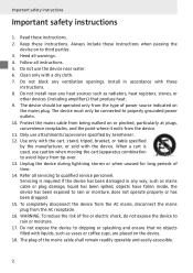
Keep these instructions. 8. Follow all warnings. 4. Do not use attachments/accessories specified by the manufacturer, or sold with a dry cloth. 7. Only use the device near any ventilation openings. Use only with the cart, stand, tripod, bracket, or table specified by Sennheiser. 12....filled with these instructions. Refer all servicing to avoid injury from tip-over. 13. Servicing is used, use caution when moving the cart/apparatus combination to qualified service personnel. The plug of time. 14. Do not install near water. 6. Protect the mains cable from the type...
Keep these instructions. 8. Follow all warnings. 4. Do not use attachments/accessories specified by the manufacturer, or sold with a dry cloth. 7. Only use the device near any ventilation openings. Use only with the cart, stand, tripod, bracket, or table specified by Sennheiser. 12....filled with these instructions. Refer all servicing to avoid injury from tip-over. 13. Servicing is used, use caution when moving the cart/apparatus combination to qualified service personnel. The plug of time. 14. Do not install near water. 6. Protect the mains cable from the type...
Instructions for Use
Page 55
... important operating and maintenance instructions in the literature accompanying this AC 3200. This symbol is opened. Refer servicing to determine that may result in fire, electric shock, or other hazards. Important safety instructions Hazard warnings on the rear of the AC 3200 active transmitter combiner 8:1 The label shown on this may be sure the service technician has used replacement parts specified by Sennheiser or...
... important operating and maintenance instructions in the literature accompanying this AC 3200. This symbol is opened. Refer servicing to determine that may result in fire, electric shock, or other hazards. Important safety instructions Hazard warnings on the rear of the AC 3200 active transmitter combiner 8:1 The label shown on this may be sure the service technician has used replacement parts specified by Sennheiser or...

Instructions for Use
Page 56
"Improper use of the device Intended use " means using the device within the operating conditions and limitations described in this instruction manual. Important safety instructions Intended use of the AC 3200 includes: y using the device for professional purposes, y having read this instruction manual especially the chapter "Important safety instructions" on page 2, y using the device other than as described in this instruction manual, or under operating conditions which differ from those described herein. 4
"Improper use of the device Intended use " means using the device within the operating conditions and limitations described in this instruction manual. Important safety instructions Intended use of the AC 3200 includes: y using the device for professional purposes, y having read this instruction manual especially the chapter "Important safety instructions" on page 2, y using the device other than as described in this instruction manual, or under operating conditions which differ from those described herein. 4
Instructions for Use
Page 57
... 1 AC 3200 active transmitter combiner 8:1 3 mains cable (EU/UK/US) 4 self-adhesive device feet 1 instruction manual 5 The AC 3200 allows you to make high-quality 8-channel transmission systems suitable for the following areas of up to eight Sennheiser wireless monitoring transmitters can be transmitted (e.g. the A 2003 UHF directional antenna, the A 1031 U omni-directional antenna or the A 5000 CP circularly polarized UHF antenna. The AC 3200 active transmitter combiner 8:1 The AC 3200 active transmitter...
... 1 AC 3200 active transmitter combiner 8:1 3 mains cable (EU/UK/US) 4 self-adhesive device feet 1 instruction manual 5 The AC 3200 allows you to make high-quality 8-channel transmission systems suitable for the following areas of up to eight Sennheiser wireless monitoring transmitters can be transmitted (e.g. the A 2003 UHF directional antenna, the A 1031 U omni-directional antenna or the A 5000 CP circularly polarized UHF antenna. The AC 3200 active transmitter combiner 8:1 The AC 3200 active transmitter...
Instructions for Use
Page 58
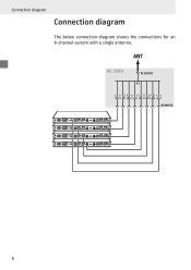
Connection diagram Connection diagram The below connection diagram shows the connections for an 8-channel system with a single antenna. AC 3200 6
Connection diagram Connection diagram The below connection diagram shows the connections for an 8-channel system with a single antenna. AC 3200 6

Instructions for Use
Page 59
Product overview · ᕢ³ Product overview 70 W ² ¶ ¶ º¶ ¶ ³ Rack mount "ears" · Air vents (on the sides) » 8 LEDs: operation indicators of the RF inputs ¿ LED ´ On/off switch ² IEC mains socket ¶ 8 RF inputs RF IN 1 to RF IN 8 for connecting the transmitters º BNC socket for antenna output ANT 7
Product overview · ᕢ³ Product overview 70 W ² ¶ ¶ º¶ ¶ ³ Rack mount "ears" · Air vents (on the sides) » 8 LEDs: operation indicators of the RF inputs ¿ LED ´ On/off switch ² IEC mains socket ¶ 8 RF inputs RF IN 1 to RF IN 8 for connecting the transmitters º BNC socket for antenna output ANT 7
Instructions for Use
Page 60
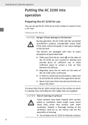
... AC 3200 on an even surface or mount it can set up the device CAUTION! Putting the AC 3200 into operation Putting the AC 3200 into operation Preparing the AC 3200 for use You can cause damage to ensure a free ...AC 3200 with other ! CAUTION! Despite a thorough testing of the synthetics used by us, we cannot rule out the possibility of the AC 3200 are supplied. Risk of staining of heat damage to install the AC 3200 as the uppermost device. ̈ Never stack more than two devices directly one above the other synthetics. During operation, the AC 3200 and the connected transmitters...
... AC 3200 on an even surface or mount it can set up the device CAUTION! Putting the AC 3200 into operation Putting the AC 3200 into operation Preparing the AC 3200 for use You can cause damage to ensure a free ...AC 3200 with other ! CAUTION! Despite a thorough testing of the synthetics used by us, we cannot rule out the possibility of the AC 3200 are supplied. Risk of staining of heat damage to install the AC 3200 as the uppermost device. ̈ Never stack more than two devices directly one above the other synthetics. During operation, the AC 3200 and the connected transmitters...
Instructions for Use
Page 61
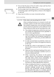
... as a severely unbalanced rack. ̈ When connecting the device to the power supply, observe the information indicated on an even, horizontal surface. Risks when rack mounting the AC 3200! Putting the AC 3200 into a rack. ̈ The ambient temperature within the rack must not exceed the temperature limit specified in the AC 3200 specifications. ̈ When installing the device in a rack, take good...
... as a severely unbalanced rack. ̈ When connecting the device to the power supply, observe the information indicated on an even, horizontal surface. Risks when rack mounting the AC 3200! Putting the AC 3200 into a rack. ̈ The ambient temperature within the rack must not exceed the temperature limit specified in the AC 3200 specifications. ̈ When installing the device in a rack, take good...
Instructions for Use
Page 62
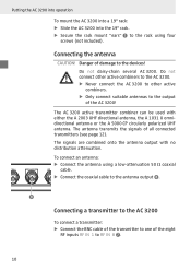
... AC 3200! Putting the AC 3200 into operation To mount the AC 3200 into a 19" rack: ̈ Slide the AC 3200 into the 19" rack. ̈ Secure the rack mount "ears" ³ to the rack using a low-attenuation 50 Ω coaxial cable. ̈ Connect the coaxial cable to the antenna output º. º Connecting a transmitter to the AC 3200 To connect a transmitter: ̈ Connect the BNC cable of the transmitter to one of the eight RF inputs...
... AC 3200! Putting the AC 3200 into operation To mount the AC 3200 into a 19" rack: ̈ Slide the AC 3200 into the 19" rack. ̈ Secure the rack mount "ears" ³ to the rack using a low-attenuation 50 Ω coaxial cable. ̈ Connect the coaxial cable to the antenna output º. º Connecting a transmitter to the AC 3200 To connect a transmitter: ̈ Connect the BNC cable of the transmitter to one of the eight RF inputs...

Instructions for Use
Page 63
... light up red. ¿ goes off switch ´ again. Note: After switch-off switch ´. To disconnect the device from the mains, pull out the mains connector from the wall socket. The AC 3200 switches on and the LED ̈ Press the on/off . ¶ 70 W Putting the AC 3200 into operation ¶ ¶ ¶ 70 W ᕦ » ¿´ Connecting the mains cable...
... light up red. ¿ goes off switch ´ again. Note: After switch-off switch ´. To disconnect the device from the mains, pull out the mains connector from the wall socket. The AC 3200 switches on and the LED ̈ Press the on/off . ¶ 70 W Putting the AC 3200 into operation ¶ ¶ ¶ 70 W ᕦ » ¿´ Connecting the mains cable...
Instructions for Use
Page 64
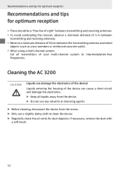
... and tips for dust deposits. Cleaning the AC 3200 CAUTION! y To avoid overloading the receiver, observe a minimum distance of sight" between the transmitting antenna and metal objects (such as cross members or reinforced-concrete walls). y When using a multi-channel system: Set all liquids away from the device. ̈ Do not use any solvents or cleansing agents. ̈ Before...
... and tips for dust deposits. Cleaning the AC 3200 CAUTION! y To avoid overloading the receiver, observe a minimum distance of sight" between the transmitting antenna and metal objects (such as cross members or reinforced-concrete walls). y When using a multi-channel system: Set all liquids away from the device. ̈ Do not use any solvents or cleansing agents. ̈ Before...
Instructions for Use
Page 65
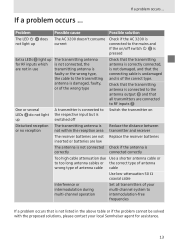
... cable attenuation due Use a shorter antenna cable or to intermodulation-free frequencies If a problem occurs that is of your local Sennheiser agent for assistance. 13 If a problem occurs ... Check that the transmitting antenna is connected to the antenna output º and that all transmitters are connected to RF inputs ¶ One or several LEDs » do not light up A transmitter is connected to the respective input but is switched off Switch the transmitter...
... cable attenuation due Use a shorter antenna cable or to intermodulation-free frequencies If a problem occurs that is of your local Sennheiser agent for assistance. 13 If a problem occurs ... Check that the transmitting antenna is connected to the antenna output º and that all transmitters are connected to RF inputs ¶ One or several LEDs » do not light up A transmitter is connected to the respective input but is switched off Switch the transmitter...

Instructions for Use
Page 66
Accessories and spare parts Accessories and spare parts The following accessories are available from your Sennheiser partner: Cat. Accessory/spare part 003658 A 2003 UHF passive directional antenna 004645 A 1031 U passive omni-directional antenna 500887 A 5000 CP circularly polarized UHF antenna 002324 GZL 1019-A1 BNC-BNC coaxial cable, type RG 58, length 1 m 14 No.
Accessories and spare parts Accessories and spare parts The following accessories are available from your Sennheiser partner: Cat. Accessory/spare part 003658 A 2003 UHF passive directional antenna 004645 A 1031 U passive omni-directional antenna 500887 A 5000 CP circularly polarized UHF antenna 002324 GZL 1019-A1 BNC-BNC coaxial cable, type RG 58, length 1 m 14 No.

Instructions for Use
Page 67
Specifications Specifications Frequency range 500 - 870 MHz Distribution attentuation 0 dB (±1 dB) RF input power nominal value up to 100 mW per input inputs protected up to max. 250 mW Impedance 50 Ω Power supply 100 V - 240 V AC, 50 - 60 Hz Power consumption max. 70 W Temperature range 0 °C to 45 °C Weight approx. 4 kg Type approvals Area USA: Canada: EU: Conformity FCC-Part 74.861...
Specifications Specifications Frequency range 500 - 870 MHz Distribution attentuation 0 dB (±1 dB) RF input power nominal value up to 100 mW per input inputs protected up to max. 250 mW Impedance 50 Ω Power supply 100 V - 240 V AC, 50 - 60 Hz Power consumption max. 70 W Temperature range 0 °C to 45 °C Weight approx. 4 kg Type approvals Area USA: Canada: EU: Conformity FCC-Part 74.861...

Instructions for Use
Page 68
... equipment and receiver. • Connect the equipment into an outlet on , the user is encouraged to try to correct the interference by Sennheiser electronic Corp. Operation is in a residential installation. These limits are designed to this equipment. may cause undesired operation. Changes or modifications made to provide reasonable protection against harmful interference in compliance with the instructions, may not...
... equipment and receiver. • Connect the equipment into an outlet on , the user is encouraged to try to correct the interference by Sennheiser electronic Corp. Operation is in a residential installation. These limits are designed to this equipment. may cause undesired operation. Changes or modifications made to provide reasonable protection against harmful interference in compliance with the instructions, may not...

Instructions for Use
Page 69
KG Am Labor 1, 30900 Wedemark, Germany Phone: +49 (5130) 600 0 Fax: +49 (5130) 600 300 www.sennheiser.com Printed in Germany Publ. 09/08 528244/A01 Sennheiser electronic GmbH & Co.
KG Am Labor 1, 30900 Wedemark, Germany Phone: +49 (5130) 600 0 Fax: +49 (5130) 600 300 www.sennheiser.com Printed in Germany Publ. 09/08 528244/A01 Sennheiser electronic GmbH & Co.

