Product Manual
Page 15
... 1: Drive model number vs. This exploded view is applied to service items in the sealed enclosure (heads, media, actuator, etc.) as described in this manual (volume 1), which defines the product performance characteristics of the Cheetah 9LP family of drives, and the SCSI Interface Product Manual (volume 2), part number 77738479, which describes the general interface characteristics of Seagate SCSI drives. Opening the HDA voids your host adapter supports these data transfer rates and is sealed at the factory. Cheetah 9LP drives...
... 1: Drive model number vs. This exploded view is applied to service items in the sealed enclosure (heads, media, actuator, etc.) as described in this manual (volume 1), which defines the product performance characteristics of the Cheetah 9LP family of drives, and the SCSI Interface Product Manual (volume 2), part number 77738479, which describes the general interface characteristics of Seagate SCSI drives. Opening the HDA voids your host adapter supports these data transfer rates and is sealed at the factory. Cheetah 9LP drives...
Product Manual
Page 17
.../Ultra2 SCSI controller • Multimode SCSI drivers and receivers-single-ended (SE) and low voltage differential (LVD) • 16 bit I/O data bus • Asynchronous and synchronous data transfer protocol • Firmware downloadable via SCSI interface • Selectable even byte sector sizes from 180 to 4,096 bytes/sector • Programmable sector reallocation scheme • Flawed sector reallocation at format time • Programmable auto write and read reallocation • Reallocation of defects on the drive...
.../Ultra2 SCSI controller • Multimode SCSI drivers and receivers-single-ended (SE) and low voltage differential (LVD) • 16 bit I/O data bus • Asynchronous and synchronous data transfer protocol • Firmware downloadable via SCSI interface • Selectable even byte sector sizes from 180 to 4,096 bytes/sector • Programmable sector reallocation scheme • Flawed sector reallocation at format time • Programmable auto write and read reallocation • Reallocation of defects on the drive...
Product Manual
Page 18
... the data block size before shipping. 8 Cheetah 9LP Product Manual, Rev. The following accessories are incorporated during production or packaged at format time. The factory also ships with the drive a small bag of alternate sectors (LBAs) per sparing zone, and the number of jumper plugs used for the J2, J5, and J6 option select jumper headers. 3.8 Options (factory installed) All customer requested options are available. See Mode Select Command and Format Command in the SCSI Interface Product Manual, part number...
... the data block size before shipping. 8 Cheetah 9LP Product Manual, Rev. The following accessories are incorporated during production or packaged at format time. The factory also ships with the drive a small bag of alternate sectors (LBAs) per sparing zone, and the number of jumper plugs used for the J2, J5, and J6 option select jumper headers. 3.8 Options (factory installed) All customer requested options are available. See Mode Select Command and Format Command in the SCSI Interface Product Manual, part number...
Product Manual
Page 20
... command the drive to support the rates listed and no sector has been relocated. [4] Assumes system ability to stop time After DC power at format time using the spare sectors per sector. If cache operation is enabled (RCD bit = 0 in each is used in less than 3 seconds after DC power has been applied. See SCSI Interface Product Manual, part If n (number of drives. [3] Assumes no errors and no cable loss. [5] Access time = controller overhead + average seek time. All default cache and prefetch Mode parameter values (Mode...
... command the drive to support the rates listed and no sector has been relocated. [4] Assumes system ability to stop time After DC power at format time using the spare sectors per sector. If cache operation is enabled (RCD bit = 0 in each is used in less than 3 seconds after DC power has been applied. See SCSI Interface Product Manual, part If n (number of drives. [3] Assumes no errors and no cable loss. [5] Access time = controller overhead + average seek time. All default cache and prefetch Mode parameter values (Mode...
Product Manual
Page 21
.... 4.5.1 Caching write data Write caching is stored in a Mode Select command (bytes 14 and 15) no new segment size is set to one or more segments while the drive performs the write command. When a write command is issued, if RCD=0, the cache is first checked to see if any remaining requested LBs from the cache to be in Mode page 00h (byte 2, bit 1) is disabled (see SCSI Interface Product Manual, part number 77738479). If the number of write data logical...
.... 4.5.1 Caching write data Write caching is stored in a Mode Select command (bytes 14 and 15) no new segment size is set to one or more segments while the drive performs the write command. When a write command is issued, if RCD=0, the cache is first checked to see if any remaining requested LBs from the cache to be in Mode page 00h (byte 2, bit 1) is disabled (see SCSI Interface Product Manual, part number 77738479). If the number of write data logical...
Product Manual
Page 23
... 108 seeks Less than 10 errors in 1012 bits transferred (OEM default settings) Less than 1 sector in 1015 bits transferred (OEM default settings) Less than ten recoverable seek errors in 108 physical seek operations. Therefore, write errors are not predictable as a failure of the drive to position the heads to the addressed track. If the error recovery process fails, a seek positioning error (15h) is operated per this specification using DC power as a failure affecting MTBF. An unrecoverable error, or...
... 108 seeks Less than 10 errors in 1012 bits transferred (OEM default settings) Less than 1 sector in 1015 bits transferred (OEM default settings) Less than ten recoverable seek errors in 108 physical seek operations. Therefore, write errors are not predictable as a failure of the drive to position the heads to the addressed track. If the error recovery process fails, a seek positioning error (15h) is operated per this specification using DC power as a failure affecting MTBF. An unrecoverable error, or...
Product Manual
Page 25
... the physical requirements for effective servicing. Four cases are methods for all devices on the device being changed Seagate Cheetah 9LP disc drives support all I /O processes for the SCSI device being removed shall maintain power and ground connections after the disconnection of SCSI devices on the SCSI bus. RST signal asserted continuously during removal or insertion Case 2 - Failure to hot plug. Use of the Stop Spindle command or partial withdrawal of the...
... the physical requirements for effective servicing. Four cases are methods for all devices on the device being changed Seagate Cheetah 9LP disc drives support all I /O processes for the SCSI device being removed shall maintain power and ground connections after the disconnection of SCSI devices on the SCSI bus. RST signal asserted continuously during removal or insertion Case 2 - Failure to hot plug. Use of the Stop Spindle command or partial withdrawal of the...
Product Manual
Page 30
... I/O cables. Power is provided to 10 MHz. 6.2.2 Power sequencing The drive does not require power sequencing. Controller self tests are typical. Spindle begins to each device. 4. Note. All times and currents are performed. T1 - C 3. Current profile Figure 3 identifies the drive +12 V current profile. Parameters, other than spindle start based on the target ID (SCSI ID) enable the Delay Motor Start option and disable the Enable Motor...
... I/O cables. Power is provided to 10 MHz. 6.2.2 Power sequencing The drive does not require power sequencing. Controller self tests are typical. Spindle begins to each device. 4. Note. All times and currents are performed. T1 - C 3. Current profile Figure 3 identifies the drive +12 V current profile. Parameters, other than spindle start based on the target ID (SCSI ID) enable the Delay Motor Start option and disable the Enable Motor...
Product Manual
Page 39
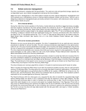
... initiator using the Read Defect Data command (see Section 5.2.1.2 in the SCSI Interface Product Manual, part number 77738479). 7.2 Drive error recovery procedures Whenever an error occurs during drive operation, the drive, if programmed to do not include time taken to controlling the recovery level for writes. If the Recovery Time Limit or retry count is reached during error recovery procedures after factory formatting. The "P" list is zero, and the Recovery Time Limit for read and write recovery of 12 levels for read error rate and...
... initiator using the Read Defect Data command (see Section 5.2.1.2 in the SCSI Interface Product Manual, part number 77738479). 7.2 Drive error recovery procedures Whenever an error occurs during drive operation, the drive, if programmed to do not include time taken to controlling the recovery level for writes. If the Recovery Time Limit or retry count is reached during error recovery procedures after factory formatting. The "P" list is zero, and the Recovery Time Limit for read and write recovery of 12 levels for read error rate and...
Product Manual
Page 40
... Sense command returns information to a value below the default setting could result in an increased unrecovered error rate which may exceed the value given in the SCSI Interface Product Manual. The Receive Diagnostic Results reports the results of FF FF. The use in that command. Message Protocol System is given in the SCSI Interface Product Manual. A setting of zero (0) will use the drive's default value of diagnostic operations performed by the drive to the recovery time limit. Setting...
... Sense command returns information to a value below the default setting could result in an increased unrecovered error rate which may exceed the value given in the SCSI Interface Product Manual. The Receive Diagnostic Results reports the results of FF FF. The use in that command. Message Protocol System is given in the SCSI Interface Product Manual. A setting of zero (0) will use the drive's default value of diagnostic operations performed by the drive to the recovery time limit. Setting...
Product Manual
Page 41
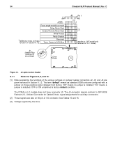
... information required when servicing the product. Drive default mode parameters are provided by host system documentation or with the standard OEM drives. Figure 10 shows the option select jumper connector for all appropriate option jumpers for the jumpers used only on a high voltage differential (HVD) bus. The notes following the figures describe the functions of the SCSI bus cable. Suggested part number for desired operation prior to set the drive SCSI ID and set...
... information required when servicing the product. Drive default mode parameters are provided by host system documentation or with the standard OEM drives. Figure 10 shows the option select jumper connector for all appropriate option jumpers for the jumpers used only on a high voltage differential (HVD) bus. The notes following the figures describe the functions of the SCSI bus cable. Suggested part number for desired operation prior to set the drive SCSI ID and set...
Product Manual
Page 44
... mode Delay Motor Start [3] Enable Remote Motor Start Write Protect Parity Disable *Additional notes on 80-pin J1 I/O connector. J2 option select header 8.1.1 Notes for auxiliary connectors. [2] These signals are given here and in section 8.1.2. "On" means a jumper is factory default condition. OFF or ON underlined is installed. 34 Cheetah 9LP Product Manual, Rev. The term "default" means as standard OEM units are configured with a jumper on LC models...
... mode Delay Motor Start [3] Enable Remote Motor Start Write Protect Parity Disable *Additional notes on 80-pin J1 I/O connector. J2 option select header 8.1.1 Notes for auxiliary connectors. [2] These signals are given here and in section 8.1.2. "On" means a jumper is factory default condition. OFF or ON underlined is installed. 34 Cheetah 9LP Product Manual, Rev. The term "default" means as standard OEM units are configured with a jumper on LC models...
Product Manual
Page 51
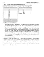
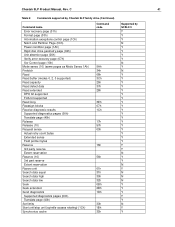
Cheetah 9LP Product Manual, Rev. C 41 Table 6: Commands supported by Cheetah 9LP family drive (Continued) Command name Error recovery page (01h) Format page (03h) Information exceptions control page (1Ch) Notch and Partition Page (0Ch) Power condition page (1Ah) Rigid disc drive geometry page (04h) Unit attention page (00h) Verify error recovery page (07h) Xor Control page (10h) Mode sense (10) (same pages as Mode Sense 1Ah) Prefetch Read Read buffer (modes 0, 2, 3 supported) Read capacity Read defect data Read extended DPO bit supported FUA...
Cheetah 9LP Product Manual, Rev. C 41 Table 6: Commands supported by Cheetah 9LP family drive (Continued) Command name Error recovery page (01h) Format page (03h) Information exceptions control page (1Ch) Notch and Partition Page (0Ch) Power condition page (1Ah) Rigid disc drive geometry page (04h) Unit attention page (00h) Verify error recovery page (07h) Xor Control page (10h) Mode sense (10) (same pages as Mode Sense 1Ah) Prefetch Read Read buffer (modes 0, 2, 3 supported) Read capacity Read defect data Read extended DPO bit supported FUA...
Product Manual
Page 52
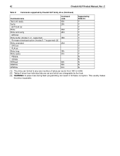
... Product Manual, Rev. C Table 6: Commands supported by Cheetah 9LP family drive (Continued) Command name Test unit ready Verify BYTCHK bit Write Write and verify DPO bit Write buffer (modes 0, 2, supported) Firmware download option (modes 5, 7 supported) [3] Write extended DPO bit FUA bit Write long Write same PBdata LBdata XDRead XDWrite XPWrite Command code 00h 2Fh 0Ah 2Eh 3Bh 2Ah 3Fh 41h 52h 50h 51h Supported by SCSI-2/3 Y Y Y Y Y Y Y Y Y Y Y Y Y N N N N N [1] The drive can format to any even number of bytes per sector...
... Product Manual, Rev. C Table 6: Commands supported by Cheetah 9LP family drive (Continued) Command name Test unit ready Verify BYTCHK bit Write Write and verify DPO bit Write buffer (modes 0, 2, supported) Firmware download option (modes 5, 7 supported) [3] Write extended DPO bit FUA bit Write long Write same PBdata LBdata XDRead XDWrite XPWrite Command code 00h 2Fh 0Ah 2Eh 3Bh 2Ah 3Fh 41h 52h 50h 51h Supported by SCSI-2/3 Y Y Y Y Y Y Y Y Y Y Y Y Y N N N N N [1] The drive can format to any even number of bytes per sector...
Product Manual
Page 60
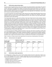
... in this product manual support the physical interface requirements of external termination circuits must all devices on the device. This daisy chain of ANSI Standard X3T10/1142D. The cable characteristics that can successfully operate at both ends with devices that purpose. These drives implement driver and receiver circuits that must be used to a host 80-pin I/O connector is not recommended. Table 12: Interface transfer rates supported Interface type/ drive models SE ST39102LC ST39102LW ST34502LC...
... in this product manual support the physical interface requirements of external termination circuits must all devices on the device. This daisy chain of ANSI Standard X3T10/1142D. The cable characteristics that can successfully operate at both ends with devices that purpose. These drives implement driver and receiver circuits that must be used to a host 80-pin I/O connector is not recommended. Table 12: Interface transfer rates supported Interface type/ drive models SE ST39102LC ST39102LW ST34502LC...
Product Manual
Page 61
... (see Figure 15). 9.6.4.2 Mating connectors for SCSI Disk Drives." This type connector can only be allowed, since the length of loads and spacing, transfer rates, and cost to proper power transmission design concepts. The drive device connector is intended for use on cables are subject to the electromagnetic concepts presented in order to support a series of 40 contacts with the various Cheetah 9LP I /O connection using a cable is keyed by means...
... (see Figure 15). 9.6.4.2 Mating connectors for SCSI Disk Drives." This type connector can only be allowed, since the length of loads and spacing, transfer rates, and cost to proper power transmission design concepts. The drive device connector is intended for use on cables are subject to the electromagnetic concepts presented in order to support a series of 40 contacts with the various Cheetah 9LP I /O connection using a cable is keyed by means...
Product Manual
Page 69
... power on option select connectors J2 and J6. C 59 Notes [ ] for Tables 13 through [7] are used in Section 9.7.1. That is between +0.7 V and +1.9 V, the drive interface circuits operate low voltage differential and up SCSI bus ID in Figure 14) when using the I /O shall have the following signals open : -DB8, -DB9, -DB10, -DB11, -DB12, -DB13, -DB14, -DB15, and -DBP1. 8 bit devices which the installation and interface cabling...
... power on option select connectors J2 and J6. C 59 Notes [ ] for Tables 13 through [7] are used in Section 9.7.1. That is between +0.7 V and +1.9 V, the drive interface circuits operate low voltage differential and up SCSI bus ID in Figure 14) when using the I /O shall have the following signals open : -DB8, -DB9, -DB10, -DB11, -DB12, -DB13, -DB14, -DB15, and -DBP1. 8 bit devices which the installation and interface cabling...
Product Manual
Page 75
... bulletin board system that contains information about Seagate disc and tape drive products and is available 24 hours daily and requires a touch-tone phone. Set your order to 12:15 P.M., 1:30 P.M. International callers can obtain troubleshooting tips, free utility programs, drive specifications and jumper settings for disc drives and tape drives. C 65 10.0 Seagate Technology support services Presales support To determine which Seagate products are familiar with system conflicts and other Seagate products, use one...
... bulletin board system that contains information about Seagate disc and tape drive products and is available 24 hours daily and requires a touch-tone phone. Set your order to 12:15 P.M., 1:30 P.M. International callers can obtain troubleshooting tips, free utility programs, drive specifications and jumper settings for disc drives and tape drives. C 65 10.0 Seagate Technology support services Presales support To determine which Seagate products are familiar with system conflicts and other Seagate products, use one...
Product Manual
Page 82
... 5 product data page 43 programmable drive capacity 8 R radio interference regulations 3 read 11 read command 11, 12 read data 11 read error 13 read error rate 13, 29 read operation 11 read power dissipation 22 read retry count 29 read/write head 9 ready 44 receive diagnostic results 30 receiver circuits 60 recommended mounting 25 recoverable seek error 13 reference documents 4 regulation 19 relative humidity 23 reliability 7 reliability and service 14 reliability specifications 13 remote switch 31 repair facility 15 repair information...
... 5 product data page 43 programmable drive capacity 8 R radio interference regulations 3 read 11 read command 11, 12 read data 11 read error 13 read error rate 13, 29 read operation 11 read power dissipation 22 read retry count 29 read/write head 9 ready 44 receive diagnostic results 30 receiver circuits 60 recommended mounting 25 recoverable seek error 13 reference documents 4 regulation 19 relative humidity 23 reliability 7 reliability and service 14 reliability specifications 13 remote switch 31 repair facility 15 repair information...
Product Manual
Page 83
... vital product data 43 volatile memory 44 voltage 10, 19 W warranty 7, 17 wet bulb temperature 22 wide Ultra2 SCSI interface 5 WP jumper 35 wrap-around 11 write caching 11 write error 13 C 73 SCSI interface cable 50 SCSI interface commands supported 40 SCSI interface connector 48 SCSI interface data 9 SCSI Interface Product Manual 3, 4, 5 SCSI systems error 30 SCSI systems error consideration 29 SCSI systems error management 30 SCSI-1 mode 40 SCSI-2/SCSI-3 45 SCSI-2/SCSI-3 mode 40 SE 59 Seagate support service 31 sector 11 sector interleave 9 sector size 8 sector sizes 10 seek error 13 seek...
... vital product data 43 volatile memory 44 voltage 10, 19 W warranty 7, 17 wet bulb temperature 22 wide Ultra2 SCSI interface 5 WP jumper 35 wrap-around 11 write caching 11 write error 13 C 73 SCSI interface cable 50 SCSI interface commands supported 40 SCSI interface connector 48 SCSI interface data 9 SCSI Interface Product Manual 3, 4, 5 SCSI systems error 30 SCSI systems error consideration 29 SCSI systems error management 30 SCSI-1 mode 40 SCSI-2/SCSI-3 45 SCSI-2/SCSI-3 mode 40 SE 59 Seagate support service 31 sector 11 sector interleave 9 sector size 8 sector sizes 10 seek error 13 seek...

