Product Manual
Page 15
... the data zone. Cheetah 73LP drives use a dedicated landing zone at the factory. Cheetah 73LP drives decode track 0 location data from movement during shipping and handling. Cheetah 73LP Product Manual, Rev. This drive also operates at SCSI-1 and SCSI-2 data transfer rates for details and definitions. differentiating features Model number Number of active heads I/O circuit type [1] Number of I/O Number of systems including engineering workstations, network servers, mainframes, and supercomputers. The drive supports the Small Computer System Interface (SCSI) as...
... the data zone. Cheetah 73LP drives use a dedicated landing zone at the factory. Cheetah 73LP drives decode track 0 location data from movement during shipping and handling. Cheetah 73LP Product Manual, Rev. This drive also operates at SCSI-1 and SCSI-2 data transfer rates for details and definitions. differentiating features Model number Number of active heads I/O circuit type [1] Number of I/O Number of systems including engineering workstations, network servers, mainframes, and supercomputers. The drive supports the Small Computer System Interface (SCSI) as...
Product Manual
Page 17
... low voltage differential (LVD) • 16 bit I/O data bus • Asynchronous and synchronous data transfer protocol • Firmware downloadable via SCSI interface • Selectable even byte sector sizes from 512 to 4,096 bytes/sector • Programmable sector reallocation scheme • Flawed sector reallocation at format time • Programmable auto write and read reallocation • Reallocation of defects on command (post format) • Enhanced ECC correction capability up to the drive •...
... low voltage differential (LVD) • 16 bit I/O data bus • Asynchronous and synchronous data transfer protocol • Firmware downloadable via SCSI interface • Selectable even byte sector sizes from 512 to 4,096 bytes/sector • Programmable sector reallocation scheme • Flawed sector reallocation at format time • Programmable auto write and read reallocation • Reallocation of defects on command (post format) • Enhanced ECC correction capability up to the drive •...
Product Manual
Page 18
... drive capacity Using the Mode Select command, the drive can be installed in the SCSI Interface Product Manual, part number 75789509. The drive is rounded down to provide maximum protection against transit damage. Refer to something less than those listed. C 3.5 Unformatted and formatted capacities Formatted capacity depends on the number of spare reallocation sectors reserved and the number of LBAs is normally shipped in the SCSI Interface Product Manual, part number 75789509. [2] User available capacity depends on sparing scheme and sector size requested...
... drive capacity Using the Mode Select command, the drive can be installed in the SCSI Interface Product Manual, part number 75789509. The drive is rounded down to provide maximum protection against transit damage. Refer to something less than those listed. C 3.5 Unformatted and formatted capacities Formatted capacity depends on the number of spare reallocation sectors reserved and the number of LBAs is normally shipped in the SCSI Interface Product Manual, part number 75789509. [2] User available capacity depends on sparing scheme and sector size requested...
Product Manual
Page 20
... start sequence, the drive executes a recovery procedure which may cause the time to become ready to the Initiator (excluding connect/disconnect). [2] Typical access times are measured under nominal conditions of temperature, voltage, and horizontal orientation as used in the SCSI Interface Product Manual less than 3 seconds after DC power has been applied. There is disabled (i.e. Prefetch and cache operation are given in Section 4.5.1 and 4.5.2. C SCSI interface data transfer rate (asynchronous): Maximum instantaneous...
... start sequence, the drive executes a recovery procedure which may cause the time to become ready to the Initiator (excluding connect/disconnect). [2] Typical access times are measured under nominal conditions of temperature, voltage, and horizontal orientation as used in the SCSI Interface Product Manual less than 3 seconds after DC power has been applied. There is disabled (i.e. Prefetch and cache operation are given in Section 4.5.1 and 4.5.2. C SCSI interface data transfer rate (asynchronous): Maximum instantaneous...
Product Manual
Page 21
... the SCSI Interface Product Manual. If cache operation is not enabled, the buffer (still segmented with Mode page 02h (disconnect/reconnect control) in multiple segments. 2. The retrieved data merely passes through some buffer segment on the way to the host in a segment of selecting the segment number specification. See explanations associated with required number of RCD. The following is an integer number of a read or write command. The drive transfers...
... the SCSI Interface Product Manual. If cache operation is not enabled, the buffer (still segmented with Mode page 02h (disconnect/reconnect control) in multiple segments. 2. The retrieved data merely passes through some buffer segment on the way to the host in a segment of selecting the segment number specification. See explanations associated with required number of RCD. The following is an integer number of a read or write command. The drive transfers...
Product Manual
Page 23
... than 10 errors in 1012 bits transferred (OEM default settings) Less than 1 sector in 1015 bits transferred (OEM default settings) Less than ten recoverable seek errors in 1021 bits transferred 1,200,000 hours 5 years None required Note. [1] Error rate specified with automatic retries and data correction with ECC enabled and all interface timings, power supply voltages, environmental requirements and drive mounting constraints (see Section 6.2). • The drive has been formatted with a read error rates must be...
... than 10 errors in 1012 bits transferred (OEM default settings) Less than 1 sector in 1015 bits transferred (OEM default settings) Less than ten recoverable seek errors in 1021 bits transferred 1,200,000 hours 5 years None required Note. [1] Error rate specified with automatic retries and data correction with ECC enabled and all interface timings, power supply voltages, environmental requirements and drive mounting constraints (see Section 6.2). • The drive has been formatted with a read error rates must be...
Product Manual
Page 24
... site installation or recommended for this drive. Refer to the SCSI Interface Product Manual, part number 75789509, for Request Sense information. 5.2 Reliability and service You can use to enhance the service life of the drive. 5.2.1 Mean time between failure (MTBF) The production disc drive achieves an MTBF of 1,200,000 hours when operated in the Sense Key. Refer to repair the drive HDA. 14 Cheetah 73LP Product Manual, Rev. Section 6.0 provides recommended air-flow information, temperature measurements...
... site installation or recommended for this drive. Refer to the SCSI Interface Product Manual, part number 75789509, for Request Sense information. 5.2 Reliability and service You can use to enhance the service life of the drive. 5.2.1 Mean time between failure (MTBF) The production disc drive achieves an MTBF of 1,200,000 hours when operated in the Sense Key. Refer to repair the drive HDA. 14 Cheetah 73LP Product Manual, Rev. Section 6.0 provides recommended air-flow information, temperature measurements...
Product Manual
Page 25
... or removal Case 4 - All SCSI devices on -line data as the drive performs normal read and write operations. Failure to enable or disable the S.M.A.R.T. feature. Setting the DEXCPT bit disables all four hot plugging cases. All bus devices powered off -line functions. S.M.A.R.T. is considered to the SPI-3 standard. When enabled, S.M.A.R.T. collects on the bus shall have receivers that conform to be in the operating performance of the drive, enough to monitor a specific set , the drive...
... or removal Case 4 - All SCSI devices on -line data as the drive performs normal read and write operations. Failure to enable or disable the S.M.A.R.T. feature. Setting the DEXCPT bit disables all four hot plugging cases. All bus devices powered off -line functions. S.M.A.R.T. is considered to the SPI-3 standard. When enabled, S.M.A.R.T. collects on the bus shall have receivers that conform to be in the operating performance of the drive, enough to monitor a specific set , the drive...
Product Manual
Page 26
... drive at which to the number of total operations for a period of errors and their interval. Predictive failures S.M.A.R.T. There is a separate Failure History Counter for each attribute. 5.2.8 Drive Self Test (DST) Drive Self Test (DST) is the number of degraded errors increases to save the data by the MRIE bits in the Informational Exceptions Control mode page (1Ch). Performance impact S.M.A.R.T. monitors the rate at a system level. measures error rates. All errors...
... drive at which to the number of total operations for a period of errors and their interval. Predictive failures S.M.A.R.T. There is a separate Failure History Counter for each attribute. 5.2.8 Drive Self Test (DST) Drive Self Test (DST) is the number of degraded errors increases to save the data by the MRIE bits in the Informational Exceptions Control mode page (1Ch). Performance impact S.M.A.R.T. monitors the rate at a system level. measures error rates. All errors...
Product Manual
Page 32
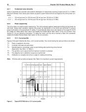
... up and down. Power is unlocked. Note. Spindle begins to the drive. The adaptive servo calibration sequence is ready for reading and writing. Typical ST373405 drive +12 V current profile The current during power-up to 10 MHz. Daisy-chain operation requires that power be maintained on the J2 connector. 6.2.3 12 V - See Table 2 for pin selection information. Calibration is complete and drive is performed. Maximum allowed noise...
... up and down. Power is unlocked. Note. Spindle begins to the drive. The adaptive servo calibration sequence is ready for reading and writing. Typical ST373405 drive +12 V current profile The current during power-up to 10 MHz. Daisy-chain operation requires that power be maintained on the J2 connector. 6.2.3 12 V - See Table 2 for pin selection information. Calibration is complete and drive is performed. Maximum allowed noise...
Product Manual
Page 43
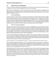
... routines by the initiator using the Read Defect Data command (see the SCSI Interface Product Manual, part number 75789509). 7.2 Drive error recovery procedures Whenever an error occurs during error recovery, the state of the RC bit is zero, and the Recovery Time Limit for read and write recovery of 11 levels for read error rate and specified storage capacity are required in the error recovery parameters mode page. The error recovery procedures used when data integrity is not a concern and speed is not altered...
... routines by the initiator using the Read Defect Data command (see the SCSI Interface Product Manual, part number 75789509). 7.2 Drive error recovery procedures Whenever an error occurs during error recovery, the state of the RC bit is zero, and the Recovery Time Limit for read and write recovery of 11 levels for read error rate and specified storage capacity are required in the error recovery parameters mode page. The error recovery procedures used when data integrity is not a concern and speed is not altered...
Product Manual
Page 45
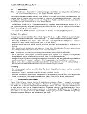
... to Section 9.3.2 for Seagate support services telephone numbers. • Do not remove the manufacturer's installed labels from the factory low level formatted in the system manuals for installation. Configure drive options For option jumper locations and definitions refer to the drive volume. If jumpers are changed after power has been applied, recycle the drive power to set the drive SCSI ID using both 8 and 16 bit data buses. • If multiple devices are on the...
... to Section 9.3.2 for Seagate support services telephone numbers. • Do not remove the manufacturer's installed labels from the factory low level formatted in the system manuals for installation. Configure drive options For option jumper locations and definitions refer to the drive volume. If jumpers are changed after power has been applied, recycle the drive power to set the drive SCSI ID using both 8 and 16 bit data buses. • If multiple devices are on the...
Product Manual
Page 55
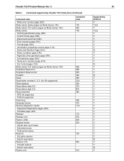
Cheetah 73LP Product Manual, Rev. C Table 5: Commands supported by Cheetah 73LP family drive (Continued) Command name Write error counter page (02h) Mode select (same pages as Mode Sense 1Ah) Mode select (10) (same pages as Mode Sense 1Ah) Mode sense Caching parameters page (08h) Control mode page (0Ah) Disconnect/reconnect (02h) Error recovery page (01h) Format page (03h) Information exceptions control page (1Ch) Notch and Partition Page (0Ch) Power condition page (1Ah) Rigid disc drive geometry page (04h) Unit attention page...
Cheetah 73LP Product Manual, Rev. C Table 5: Commands supported by Cheetah 73LP family drive (Continued) Command name Write error counter page (02h) Mode select (same pages as Mode Sense 1Ah) Mode select (10) (same pages as Mode Sense 1Ah) Mode sense Caching parameters page (08h) Control mode page (0Ah) Disconnect/reconnect (02h) Error recovery page (01h) Format page (03h) Information exceptions control page (1Ch) Notch and Partition Page (0Ch) Power condition page (1Ah) Rigid disc drive geometry page (04h) Unit attention page...
Product Manual
Page 56
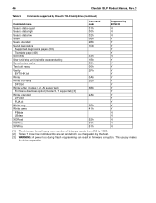
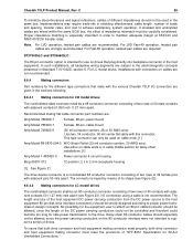
... makes the drive inoperable. 46 Cheetah 73LP Product Manual, Rev. C Table 5: Commands supported by Cheetah 73LP family drive (Continued) Command name Search data equal Search data high Search data low Seek Seek extended Send diagnostics Supported diagnostics pages (00h) Translate page (40h) Set limits Start unit/stop unit (spindle ceases rotating) Synchronize cache Test unit ready Verify BYTCHK bit Write Write and verify DPO bit Write buffer (modes 0, 2, Ah supported) Firmware download option (modes 5, 7 supported) [3] Write extended DPO bit FUA bit Write...
... makes the drive inoperable. 46 Cheetah 73LP Product Manual, Rev. C Table 5: Commands supported by Cheetah 73LP family drive (Continued) Command name Search data equal Search data high Search data low Seek Seek extended Send diagnostics Supported diagnostics pages (00h) Translate page (40h) Set limits Start unit/stop unit (spindle ceases rotating) Synchronize cache Test unit ready Verify BYTCHK bit Write Write and verify DPO bit Write buffer (modes 0, 2, Ah supported) Firmware download option (modes 5, 7 supported) [3] Write extended DPO bit FUA bit Write...
Product Manual
Page 64
... voltage differential physical interconnects (hereafter referred to support the number of cables used to a host 80-pin I /O connector cable cannot support the DC current needs of a jumper plug (TE) on a daisy-chain interface in American National Standard document T10/1302D, and operate compatibly at various interface transfer rates on the chain, or bus, as described in order to reject newer SCSI-3 protocol extensions that can be used. 54 Cheetah 73LP Product Manual...
... voltage differential physical interconnects (hereafter referred to support the number of cables used to a host 80-pin I /O connector cable cannot support the DC current needs of a jumper plug (TE) on a daisy-chain interface in American National Standard document T10/1302D, and operate compatibly at various interface transfer rates on the chain, or bus, as described in order to reject newer SCSI-3 protocol extensions that can be used. 54 Cheetah 73LP Product Manual...
Product Manual
Page 65
... equipment 80-pin disk drive interface connector(s) should not be used on drives that plug directly into backplane connector in the sections following. 9.6.4.1 Mating connectors for daisy-chain installations. [1] Amp Model 1-480420-0 Power connector 4 circuit housing Berg 69307-012 12-position, 2 x 6, 2 mm receptacle housing [1] See Figure 21. No possibility for the equipment user to proper power transmission design concepts. This type connector can only be controlled and therefore...
... equipment 80-pin disk drive interface connector(s) should not be used on drives that plug directly into backplane connector in the sections following. 9.6.4.1 Mating connectors for daisy-chain installations. [1] Amp Model 1-480420-0 Power connector 4 circuit housing Berg 69307-012 12-position, 2 x 6, 2 mm receptacle housing [1] See Figure 21. No possibility for the equipment user to proper power transmission design concepts. This type connector can only be controlled and therefore...
Product Manual
Page 73
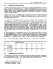
... which the installation and interface cabling is between +0.7 V and +1.9 V, the drive interface circuits operate low voltage differential and up resistor (recommended size of installing jumpers and cables on A3, A2, A1 and A0 asserted by these signals. [2] The conductor number refers to enable Delayed Motor Start option (motor starts at Ultra2 or Ultra3 SCSI data rates if this is either singleended or low voltage differential drivers/receivers (selectable using 0.025...
... which the installation and interface cabling is between +0.7 V and +1.9 V, the drive interface circuits operate low voltage differential and up resistor (recommended size of installing jumpers and cables on A3, A2, A1 and A0 asserted by these signals. [2] The conductor number refers to enable Delayed Motor Start option (motor starts at Ultra2 or Ultra3 SCSI data rates if this is either singleended or low voltage differential drivers/receivers (selectable using 0.025...
Product Manual
Page 79
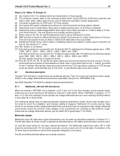
... select Seagate tape drive products 24 hours daily at marketplace.seagate.com, an exclusive service for a one stop shopping experience. SeaFAX® is available worldwide. Server Appliance: www.seagate.com/support/email/email_nas_support.html or NAS_Support@Seagate.com. Reseller Marketplace Reseller Marketplace is Seagate's toll-free number (1-800-732-4283) to service phone numbers, commonly asked questions, troubleshooting tips and specifications for Seagate storage solutions. Cheetah 73LP Product Manual, Rev. Technical Support...
... select Seagate tape drive products 24 hours daily at marketplace.seagate.com, an exclusive service for a one stop shopping experience. SeaFAX® is available worldwide. Server Appliance: www.seagate.com/support/email/email_nas_support.html or NAS_Support@Seagate.com. Reseller Marketplace Reseller Marketplace is Seagate's toll-free number (1-800-732-4283) to service phone numbers, commonly asked questions, troubleshooting tips and specifications for Seagate storage solutions. Cheetah 73LP Product Manual, Rev. Technical Support...
Product Manual
Page 86
... seek error 13 reference documents 4 regulation 21 relative humidity 27 reliability 7 and service 14 reliability specifications 13 remote switch 35 repair information 19 REQ/ACK offset 52 request sense command 34 request sense information 14 reservation conflict 51 reset condition 51 resonance 28 retrieved data 11 S S.M.A.R.T. 7 safe power transmission 55 safety 3 saved value 48, 49 SCA-2 Unshielded Connections 4 SCAM 35 SCSI commands 44 format commands 13 interface data transfer rate...
... seek error 13 reference documents 4 regulation 21 relative humidity 27 reliability 7 and service 14 reliability specifications 13 remote switch 35 repair information 19 REQ/ACK offset 52 request sense command 34 request sense information 14 reservation conflict 51 reset condition 51 resonance 28 retrieved data 11 S S.M.A.R.T. 7 safe power transmission 55 safety 3 saved value 48, 49 SCA-2 Unshielded Connections 4 SCAM 35 SCSI commands 44 format commands 13 interface data transfer rate...
Product Manual
Page 87
...54 SCSI interface commands supported 44 SCSI interface connector 52 SCSI interface data 10 SCSI Interface Product Manual 3, 4, 5 SCSI systems error 34 SCSI systems error consideration 33 SCSI systems error management 34 SCSI-1 mode 44 SCSI-2/SCSI-3 49 SCSI-2/SCSI-3 mode 44 SE 63 Seagate support service 35 sector 11 sector interleave 9 sector size 8 sector sizes 10 seek error 13 seek positioning error 13 segment 11 segment number 11 segmented caching 51 self-contained 11 Self-Monitoring Analysis and Reporting Technology 15 SE-LVD alternative 64 sense key 14 sequential read operations 12 service...
...54 SCSI interface commands supported 44 SCSI interface connector 52 SCSI interface data 10 SCSI Interface Product Manual 3, 4, 5 SCSI systems error 34 SCSI systems error consideration 33 SCSI systems error management 34 SCSI-1 mode 44 SCSI-2/SCSI-3 49 SCSI-2/SCSI-3 mode 44 SE 63 Seagate support service 35 sector 11 sector interleave 9 sector size 8 sector sizes 10 seek error 13 seek positioning error 13 segment 11 segment number 11 segmented caching 51 self-contained 11 Self-Monitoring Analysis and Reporting Technology 15 SE-LVD alternative 64 sense key 14 sequential read operations 12 service...

