Product Manual
Page 9
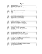
...for W/WD drives 40 Figure 17. Recommended mounting 42 Figure 19. ST15150N/ND drives option select jumper connectors 48 Figure 21. ST15150W/WD drives option header ...locations 50 Figure 22. SCSI reference index signal driver/receiver combination 55 Figure 26. ST15150W/WD drives configuration select header specification 56 Figure 28. Synchronized reference signal characteristics 18 Figure 6. Wide SCSI device connector 78 Figure 35. Figures Figure 1. Barracuda disc drive...
...for W/WD drives 40 Figure 17. Recommended mounting 42 Figure 19. ST15150N/ND drives option select jumper connectors 48 Figure 21. ST15150W/WD drives option header ...locations 50 Figure 22. SCSI reference index signal driver/receiver combination 55 Figure 26. ST15150W/WD drives configuration select header specification 56 Figure 28. Synchronized reference signal characteristics 18 Figure 6. Wide SCSI device connector 78 Figure 35. Figures Figure 1. Barracuda disc drive...

Product Manual
Page 19
...new settings effective. Internal termination is available on single-ended (ST15150N/ W/WC) drives by other devices, and the new drive is not attached to the end of the SCSI bus cable. If you change jumpers after applying power, recycle the drive's power to Figures 20, 22, or 24. You ...the factory low-level formatted in 512-byte sectors. • Reformat the drive if: a. The drive is not presently used by enabling this drive. Refer to low-level format this feature with a jumper (see Section 10). ST15150N/ND/W/WD/WC/DC Product Manual, Rev. Formatting • It is the...
...new settings effective. Internal termination is available on single-ended (ST15150N/ W/WC) drives by other devices, and the new drive is not attached to the end of the SCSI bus cable. If you change jumpers after applying power, recycle the drive's power to Figures 20, 22, or 24. You ...the factory low-level formatted in 512-byte sectors. • Reformat the drive if: a. The drive is not presently used by enabling this drive. Refer to low-level format this feature with a jumper (see Section 10). ST15150N/ND/W/WD/WC/DC Product Manual, Rev. Formatting • It is the...

Product Manual
Page 41
... the TRMPWR signal on the same SCSI bus must have ceased (for ST15150WC and ST15150DC drives, all term power jumpers accomplishes this. The power to the electronics and mechanics of the systems integrator to assure that conform ...ST15150N/ND/W/WD/WC/DC Product Manual, Rev. During power-up and power-down periods, the hot SCSI connect/disconnect capability does not produce glitches or any corruptions on a carrier or tray, discharge the static electricity from the drive, and wait for simultaneous power disconnection and physical removal. D 31 6.2.8 Hot plugging Barracuda 4 disc drives...
... the TRMPWR signal on the same SCSI bus must have ceased (for ST15150WC and ST15150DC drives, all term power jumpers accomplishes this. The power to the electronics and mechanics of the systems integrator to assure that conform ...ST15150N/ND/W/WD/WC/DC Product Manual, Rev. During power-up and power-down periods, the hot SCSI connect/disconnect capability does not produce glitches or any corruptions on a carrier or tray, discharge the static electricity from the drive, and wait for simultaneous power disconnection and physical removal. D 31 6.2.8 Hot plugging Barracuda 4 disc drives...
Product Manual
Page 58
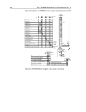
.../W/WD/WC/DC Product Manual, Rev. power to external terminator. power to SCSI bus. ST15150N/ND drives option select jumper connectors SCSI Connector J4 Pin 1 SCSI ID = 0 (default) SCSI ID = 1 SCSI ID = 2 SCSI ID = 3 ...drive terminator. power from drive. Term. Figure 20. Host adapter or other device provides term. power to SCSI bus. Term. Term. power to SCSI bus and drive. D Figure 20 illustrates ST15150N/ND drives option select jumper connectors. ST15150ND Pin 1 J01 Pin 2 Enable drive terminator. ST15150N Pin 3 Pin 1 J01 Pin 2 ST15150N...
.../W/WD/WC/DC Product Manual, Rev. power to external terminator. power to SCSI bus. ST15150N/ND drives option select jumper connectors SCSI Connector J4 Pin 1 SCSI ID = 0 (default) SCSI ID = 1 SCSI ID = 2 SCSI ID = 3 ...drive terminator. power from drive. Term. Figure 20. Host adapter or other device provides term. power to SCSI bus. Term. Term. power to SCSI bus and drive. D Figure 20 illustrates ST15150N/ND drives option select jumper connectors. ST15150ND Pin 1 J01 Pin 2 Enable drive terminator. ST15150N Pin 3 Pin 1 J01 Pin 2 ST15150N...

Product Manual
Page 59
...spindle motor starts in thirty (30) seconds. No jumper installed causes the unit to be disabled. Host adapter or other device on ST15150N/ND drives Default is no jumper. J4 1 & 2 Spindle sync cable connector. Jumper installed causes parity checking and error reporting to look... power to the SCSI bus. D 49 ST15150N J01 option jumpers Block Pins Function J01 1& 2 Terminator enable. 3 & 4 Terminator power to the SCSI bus. 5 & 6 Terminator power from the drive. Jumper installed write protects the entire disc drive. Jumper installed waits for 10 seconds for the Start...
...spindle motor starts in thirty (30) seconds. No jumper installed causes the unit to be disabled. Host adapter or other device on ST15150N/ND drives Default is no jumper. J4 1 & 2 Spindle sync cable connector. Jumper installed causes parity checking and error reporting to look... power to the SCSI bus. D 49 ST15150N J01 option jumpers Block Pins Function J01 1& 2 Terminator enable. 3 & 4 Terminator power to the SCSI bus. 5 & 6 Terminator power from the drive. Jumper installed write protects the entire disc drive. Jumper installed waits for 10 seconds for the Start...
Product Manual
Page 61
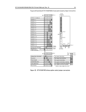
...SCSI bus. power to SCSI bus and drive. D 51 Figure 22 illustrates ST15150W/WD drives option select jumper connectors. power to external terminator. * Valid for single-ended drives only. Pin 1 Pin 2 Figure 22. power to SCSI bus. * Term. ST15150W/WD drives option select jumper connectors J5 SCSI ID = 0 (default...SCSI Connector Pin 1 J5 Pin 1 Negative (cathode) Positive (anode) Pin 1 Pin 1 Pin 1 Power J4 J01 Connector J4 Enable Drive Terminator* Reserved Parity Disable Enable Motor Start Delay Motor Start Write Protect Pin 1 Pin 3 J01 * Term. Host adapter or other device ...
...SCSI bus. power to SCSI bus and drive. D 51 Figure 22 illustrates ST15150W/WD drives option select jumper connectors. power to external terminator. * Valid for single-ended drives only. Pin 1 Pin 2 Figure 22. power to SCSI bus. * Term. ST15150W/WD drives option select jumper connectors J5 SCSI ID = 0 (default...SCSI Connector Pin 1 J5 Pin 1 Negative (cathode) Positive (anode) Pin 1 Pin 1 Pin 1 Power J4 J01 Connector J4 Enable Drive Terminator* Reserved Parity Disable Enable Motor Start Delay Motor Start Write Protect Pin 1 Pin 3 J01 * Term. Host adapter or other device ...

Product Manual
Page 62
...ST15150N/ND/W/WD/WC/DC Product Manual, Rev. J4 1 & 2 Write Protect option. Jumper installed waits for 10 seconds for each target ID number plus a maximum power-up delay of the J01 pins). Jumper installed causes parity checking and error reporting to the SCSI bus and drive. 2 & 4* - Default is no jumper... power supplied from the drive. 2 & 4* Terminator power supplied from the SCSI host. Jumper installed write protects the entire disc drive. Default is no jumper. Jumper installed causes the target to look at the Delay Motor Start jumper. No jumper installed causes the unit to...
...ST15150N/ND/W/WD/WC/DC Product Manual, Rev. J4 1 & 2 Write Protect option. Jumper installed waits for 10 seconds for each target ID number plus a maximum power-up delay of the J01 pins). Jumper installed causes parity checking and error reporting to the SCSI bus and drive. 2 & 4* - Default is no jumper... power supplied from the drive. 2 & 4* Terminator power supplied from the SCSI host. Jumper installed write protects the entire disc drive. Default is no jumper. Jumper installed causes the target to look at the Delay Motor Start jumper. No jumper installed causes the unit to...
Product Manual
Page 63
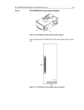
J6 Pin 1 J4 Figure 24. ST15150N/ND/W/WD/WC/DC Product Manual, Rev. ST15150WC/DC drives option header locations Figure 24 illustrates ST15150WC/DC drives option select jumper connectors. ST15150WC/DC drives option select connectors D 53 10.1.3 ST15150WC/DC drives option headers J6 J4 Figure 23.
J6 Pin 1 J4 Figure 24. ST15150N/ND/W/WD/WC/DC Product Manual, Rev. ST15150WC/DC drives option header locations Figure 24 illustrates ST15150WC/DC drives option select jumper connectors. ST15150WC/DC drives option select connectors D 53 10.1.3 ST15150WC/DC drives option headers J6 J4 Figure 23.
Product Manual
Page 67
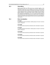
.../W/WD/WC/DC Product Manual, Rev. ST15150WD You must provide external drive termination when termination is the system designer's responsibility. 10.4 Drive termination ST15150N To enable internal drive termination, install a jumper on J4 pins 11 and 12 as shown in the Barracuda 4 family drives-do not want the system chassis to be connected to the HDA/PCB...
.../W/WD/WC/DC Product Manual, Rev. ST15150WD You must provide external drive termination when termination is the system designer's responsibility. 10.4 Drive termination ST15150N To enable internal drive termination, install a jumper on J4 pins 11 and 12 as shown in the Barracuda 4 family drives-do not want the system chassis to be connected to the HDA/PCB...

Product Manual
Page 70
...Verify Command code 40h 39h 18h 3Ah Format Unit [1] 04h Inquiry 12h Date Code Page Firmware Numbers Page Implemented Operating Def. Page Jumper Settings Page Unit Serial Number Page Vital Product Data Page Lock-Unlock-Cache 36h Log Select 4Ch Log Sense 4Dh Mode Select (6) ...SCSI-2 modes. D SCSI interface commands supported Table 5 lists the SCSI interface commands supported in SCSI-2 mode. 60 11.3 ST15150N/ND/W/WD/WC/DC Product Manual, Rev. Barracuda 4 family drives can be changed back and forth between SCSI-1 and SCSI-2 modes by ASA I ASA I ASA II SCSI-1 SCSI-2 SCSI...
...Verify Command code 40h 39h 18h 3Ah Format Unit [1] 04h Inquiry 12h Date Code Page Firmware Numbers Page Implemented Operating Def. Page Jumper Settings Page Unit Serial Number Page Vital Product Data Page Lock-Unlock-Cache 36h Log Select 4Ch Log Sense 4Dh Mode Select (6) ...SCSI-2 modes. D SCSI interface commands supported Table 5 lists the SCSI interface commands supported in SCSI-2 mode. 60 11.3 ST15150N/ND/W/WD/WC/DC Product Manual, Rev. Barracuda 4 family drives can be changed back and forth between SCSI-1 and SCSI-2 modes by ASA I ASA I ASA II SCSI-1 SCSI-2 SCSI...

Product Manual
Page 82
...-level output current = −55 milliamps Differential signals All differential interface signals consist of active terminator circuits. Output characteristics Each signal driven by ST15150WD drives are defined as follows: Logic level Driver output Receiver input Negated (0) ≥ 2.5V : ≤ 5.25V ≥ 2.0V : < ...0V The difference in the voltages between input and output signals is VR1 which has an input source voltage selected by a jumper. 72 11.7.3.2 ST15150N/ND/W/WD/WC/DC Product Manual, Rev. Single-ended transmitters and receivers Notes: [1] Part of two lines denoted +...
...-level output current = −55 milliamps Differential signals All differential interface signals consist of active terminator circuits. Output characteristics Each signal driven by ST15150WD drives are defined as follows: Logic level Driver output Receiver input Negated (0) ≥ 2.5V : ≤ 5.25V ≥ 2.0V : < ...0V The difference in the voltages between input and output signals is VR1 which has an input source voltage selected by a jumper. 72 11.7.3.2 ST15150N/ND/W/WD/WC/DC Product Manual, Rev. Single-ended transmitters and receivers Notes: [1] Part of two lines denoted +...
Product Manual
Page 84
...each end of the daisy chain. D Terminator requirements ST15150N drives Internal disc drive I/O termination consists of active circuits contained in permanently mounted IC terminator packs on the PCB. ST15150W drives Internal disc drive I /O Barracuda drives do not have provisions to accept terminator power using pin...to the SCSI bus, or to terminate the initiator and drive. Remove the Enable Drive Terminator jumper on J4 pins 11 and 12 when terminators are not required. ST15150ND/WD/DC drives Differential I /O termination consists of active circuits contained in ...
...each end of the daisy chain. D Terminator requirements ST15150N drives Internal disc drive I/O termination consists of active circuits contained in permanently mounted IC terminator packs on the PCB. ST15150W drives Internal disc drive I /O Barracuda drives do not have provisions to accept terminator power using pin...to the SCSI bus, or to terminate the initiator and drive. Remove the Enable Drive Terminator jumper on J4 pins 11 and 12 when terminators are not required. ST15150ND/WD/DC drives Differential I /O termination consists of active circuits contained in ...

Product Manual
Page 98
...the 28, 29, 30 head switch overhead time 14 heat/power dissipation 36 hot plugging Barracuda disc drives 31 humidity 36 I I/O circuits 69 index signal 18 inquiry data 62 installation 30 ...instructions 9 interface requirements 59 interleave 7 minimum sector 14 internal termination 9 internal data rate 11 J J01 jumper connector J4 jumper connector 49 49, 52 J5 jumper connector 52 jumper... ST15150N/ND 33 option/configuration headers 47 options drive temination 57 single-unit shipping pack 8 overhead time 14 ...
...the 28, 29, 30 head switch overhead time 14 heat/power dissipation 36 hot plugging Barracuda disc drives 31 humidity 36 I I/O circuits 69 index signal 18 inquiry data 62 installation 30 ...instructions 9 interface requirements 59 interleave 7 minimum sector 14 internal termination 9 internal data rate 11 J J01 jumper connector J4 jumper connector 49 49, 52 J5 jumper connector 52 jumper... ST15150N/ND 33 option/configuration headers 47 options drive temination 57 single-unit shipping pack 8 overhead time 14 ...


