
Owner's Manual
Page 2
...can pedal your progress by tracking time, speed, distance and approximate Calories burned. So let's get started in good shape, this Schwinn® bike is designed to be able to a slimmer and healthier body. The on-board digital computer enables you to accurately monitor your way ...to rely on Schwinn® craftsmanship and durability as you for making the Schwinn® bike a part of fitness. Also included are already in an exercise program or are general fitness guidelines. For years to...
...can pedal your progress by tracking time, speed, distance and approximate Calories burned. So let's get started in good shape, this Schwinn® bike is designed to be able to a slimmer and healthier body. The on-board digital computer enables you to accurately monitor your way ...to rely on Schwinn® craftsmanship and durability as you for making the Schwinn® bike a part of fitness. Also included are already in an exercise program or are general fitness guidelines. For years to...
Owner's Manual
Page 4
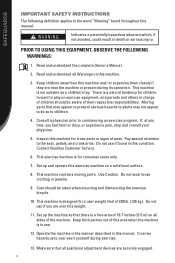
... described in this manual: Indicates a potentially hazardous situation which, if not avoided, could result in death or serious injury. Moving parts that all sides of wear. If, at any time, you are over exert yourself during its operation. This machine is a natural tendency for... loose parts or signs of the machine. Set up and operate this machine. 3. Read and understand the complete Owner's Manual. 2. Consult a physician ...
... described in this manual: Indicates a potentially hazardous situation which, if not avoided, could result in death or serious injury. Moving parts that all sides of wear. If, at any time, you are over exert yourself during its operation. This machine is a natural tendency for... loose parts or signs of the machine. Set up and operate this machine. 3. Read and understand the complete Owner's Manual. 2. Consult a physician ...
Owner's Manual
Page 24
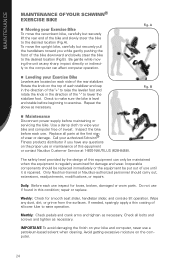
To move the recumbent bike, carefully but securely pull the handlebars toward you have any questions on the proper use until it is level and stable before beginning to exercise. ... the top of each use inspect for loose, broken, damaged or worn parts. MAINTENANCE MAINTENANCE OF YOUR SCHWINN® EXERCISE BIKE Moving your Exercise Bike To move the upright bike, carefully but securely lift the rear end of the bike and slowly steer the bike to the desired location (Fig A). Fig. Check to make sure the...
To move the recumbent bike, carefully but securely pull the handlebars toward you have any questions on the proper use until it is level and stable before beginning to exercise. ... the top of each use inspect for loose, broken, damaged or worn parts. MAINTENANCE MAINTENANCE OF YOUR SCHWINN® EXERCISE BIKE Moving your Exercise Bike To move the upright bike, carefully but securely lift the rear end of the bike and slowly steer the bike to the desired location (Fig A). Fig. Check to make sure the...
Owner's Manual
Page 26
... of your family. Remember, if you don't enjoy the space you are over 30, have health problems or have done in your schedule. Make fitness a part of heart disease in 90 days or a year? 26 Set goals.
... of your family. Remember, if you don't enjoy the space you are over 30, have health problems or have done in your schedule. Make fitness a part of heart disease in 90 days or a year? 26 Set goals.
Owner's Manual
Page 28
... into your strength training workouts by switching back and forth every couple of weight options in a revolutionary all these exercises at any time. The best part is being able to incorporate into our daily lives because it is recommended that you do everything you need complicated equipment or fancy machines. You...
... into your strength training workouts by switching back and forth every couple of weight options in a revolutionary all these exercises at any time. The best part is being able to incorporate into our daily lives because it is recommended that you do everything you need complicated equipment or fancy machines. You...
Owner's Manual
Page 37
...replacing defective frames. 3. will have the option to repair or replace any equipment frame that need to be free from the Authorized Schwinn® Dealer is expressly limited to the replacement of goods not complying with this warranty or, at Nautilus, Inc.'s election, to... liable for any warranty coverage set forth herein, whether express or implied by the use a replacement part not supplied by Schwinn® Fitness warranty policies and procedures. or an authorized Schwinn® Fitness Dealer. shall not be liable for incidental or consequential losses, damages or expenses in...
...replacing defective frames. 3. will have the option to repair or replace any equipment frame that need to be free from the Authorized Schwinn® Dealer is expressly limited to the replacement of goods not complying with this warranty or, at Nautilus, Inc.'s election, to... liable for any warranty coverage set forth herein, whether express or implied by the use a replacement part not supplied by Schwinn® Fitness warranty policies and procedures. or an authorized Schwinn® Fitness Dealer. shall not be liable for incidental or consequential losses, damages or expenses in...

Assembly Manual
Page 4
CONTENTS Table of Contents Hardware 2 Exploded View 4 Parts List 5 Assembly Instructions 6 Important Contact Numbers 21 1
CONTENTS Table of Contents Hardware 2 Exploded View 4 Parts List 5 Assembly Instructions 6 Important Contact Numbers 21 1
Assembly Manual
Page 5
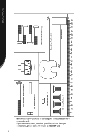
HARDWARE Note: Please verify you are missing items, are short quantities, or have all correct parts and quantities before assembling unit. If you have damaged components, please contact Schwinn at 1.800.864.1270 2 I-10 Carriage Bolt M8xP1.25x85MM (1) I-1 M8xP1.25x85mm I-4 lock nut for M8 � (1) I-2 Knob (1) I-7 Allen Bolt M8xP1.0x45mm (4) Screwdriver I-6 Screws M8x16mm Socket Wrench���� ����
HARDWARE Note: Please verify you are missing items, are short quantities, or have all correct parts and quantities before assembling unit. If you have damaged components, please contact Schwinn at 1.800.864.1270 2 I-10 Carriage Bolt M8xP1.25x85MM (1) I-1 M8xP1.25x85mm I-4 lock nut for M8 � (1) I-2 Knob (1) I-7 Allen Bolt M8xP1.0x45mm (4) Screwdriver I-6 Screws M8x16mm Socket Wrench���� ����
Assembly Manual
Page 6
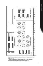
Note: Please verify you are missing items, are short quantities, or have all correct parts and quantities before assembling unit. If you have damaged components, please contact Schwinn at 1.800.864.1270 3 I-7 Allen Bolt M8xP1.0x45mm (4) Allen Key���� 4) I-3 Regular Washer 8*16*2t(15) I-5 Allen Bolt M8xP1.25x16mm (5) ���� HARDWARE
Note: Please verify you are missing items, are short quantities, or have all correct parts and quantities before assembling unit. If you have damaged components, please contact Schwinn at 1.800.864.1270 3 I-7 Allen Bolt M8xP1.0x45mm (4) Allen Key���� 4) I-3 Regular Washer 8*16*2t(15) I-5 Allen Bolt M8xP1.25x16mm (5) ���� HARDWARE
Assembly Manual
Page 8
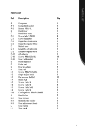
PARTS LIST PARTS LIST Ref. Description Qty A Computer 1 A-1 Computer bracket 1 A-2 Screw M5x14L 4 B Handlebar 1 C Handlebar mast 1 C-1 Screw M8x1.25X16 4 C-2 Curved Washer 4 C-3 Upper heart rate wire 1 C-4 Upper Computer Wire 1 D Main ...
PARTS LIST PARTS LIST Ref. Description Qty A Computer 1 A-1 Computer bracket 1 A-2 Screw M5x14L 4 B Handlebar 1 C Handlebar mast 1 C-1 Screw M8x1.25X16 4 C-2 Curved Washer 4 C-3 Upper heart rate wire 1 C-4 Upper Computer Wire 1 D Main ...
Assembly Manual
Page 10
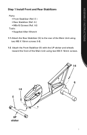
G ) • M8x16 Screws (Ref. I-6 G I -6). 1-2 Attach the Front Stabilizer (E) with the UP sticker and wheels toward the front of the Main Unit using two M8 X 16mm screws (I -6 E UP sticker 7 I-6) Tools: • Supplied Allen Wrench 1-1 Attach the Rear Stabilizer (G) to the rear of the Main Unit using two M8 X 16mm screws. E ) • Rear Stabilizer (Ref. ASSEMBLY INSTRUCTIONS Step 1 Install Front and Rear Stabilizers Parts: • Front Stabilizer (Ref.
G ) • M8x16 Screws (Ref. I-6 G I -6). 1-2 Attach the Front Stabilizer (E) with the UP sticker and wheels toward the front of the Main Unit using two M8 X 16mm screws (I -6 E UP sticker 7 I-6) Tools: • Supplied Allen Wrench 1-1 Attach the Rear Stabilizer (G) to the rear of the Main Unit using two M8 X 16mm screws. E ) • Rear Stabilizer (Ref. ASSEMBLY INSTRUCTIONS Step 1 Install Front and Rear Stabilizers Parts: • Front Stabilizer (Ref.
Assembly Manual
Page 11
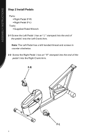
Note: The Left Pedal has a left handed thread and screws in counter clockwise. 2-2 Screw the Right Pedal ( has an "R "stamped into the end of the pedal ) into the Right Crank Arm. ASSEMBLY INSTRUCTIONS Step 2 Install Pedals Parts: • Right Pedal (F-R) • Right Pedal (F-L) Tools: • Supplied Pedal Wrench 2-1 Screw the Left Pedal ( has an "L" stamped into the end of the pedal ) into the Left Crank Arm. F-R F-L 8
Note: The Left Pedal has a left handed thread and screws in counter clockwise. 2-2 Screw the Right Pedal ( has an "R "stamped into the end of the pedal ) into the Right Crank Arm. ASSEMBLY INSTRUCTIONS Step 2 Install Pedals Parts: • Right Pedal (F-R) • Right Pedal (F-L) Tools: • Supplied Pedal Wrench 2-1 Screw the Left Pedal ( has an "L" stamped into the end of the pedal ) into the Left Crank Arm. F-R F-L 8
Assembly Manual
Page 12
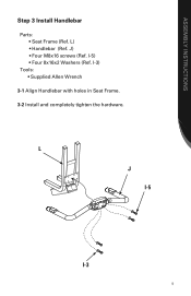
L J I-5 I -5) • Four 8x16x2 Washers (Ref. ASSEMBLY INSTRUCTIONS Step 3 Install Handlebar Parts: • Seat Frame (Ref. J) • Four M8x16 screws (Ref. I -3 9 I-3) Tools: • Supplied Allen Wrench 3-1 Align Handlebar with holes in Seat Frame. 3-2 Install and completely tighten the hardware. L) • Handlebar (Ref.
L J I-5 I -5) • Four 8x16x2 Washers (Ref. ASSEMBLY INSTRUCTIONS Step 3 Install Handlebar Parts: • Seat Frame (Ref. J) • Four M8x16 screws (Ref. I -3 9 I-3) Tools: • Supplied Allen Wrench 3-1 Align Handlebar with holes in Seat Frame. 3-2 Install and completely tighten the hardware. L) • Handlebar (Ref.
Assembly Manual
Page 13
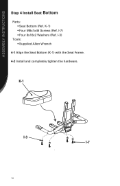
I -7 10 ASSEMBLY INSTRUCTIONS Step 4 Install Seat Bottom Parts: • Seat Bottom (Ref. K-1 I-3 I -3) Tools: • Supplied Allen Wrench 4-1 Align the Seat Bottom (K-1) with the Seat Frame. 4-2 Install and completely tighten the hardware. I-7) • Four 8x16x2 Washers (Ref. K-1) • Four M8x1x45 Screws (Ref.
I -7 10 ASSEMBLY INSTRUCTIONS Step 4 Install Seat Bottom Parts: • Seat Bottom (Ref. K-1 I-3 I -3) Tools: • Supplied Allen Wrench 4-1 Align the Seat Bottom (K-1) with the Seat Frame. 4-2 Install and completely tighten the hardware. I-7) • Four 8x16x2 Washers (Ref. K-1) • Four M8x1x45 Screws (Ref.
Assembly Manual
Page 14
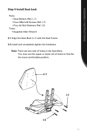
Note: There are two sets of holes to find the the most comfortable position. You may use the upper or lower set of holes in the Seat Back. ASSEMBLY INSTRUCTIONS Step 5 Install Seat back Parts: • Seat Bottom (Ref. I -3) Tools: • Supplied Allen Wrench 5-1 Align the Seat Back (L-1) with the Seat Frame. 5-2 Install and completely tighten the hardware. I -7) • Four 8x16x2 Washers (Ref. L-1) • Four M8x1x45 Screws (Ref. L-1 I-7 I-3 11
Note: There are two sets of holes to find the the most comfortable position. You may use the upper or lower set of holes in the Seat Back. ASSEMBLY INSTRUCTIONS Step 5 Install Seat back Parts: • Seat Bottom (Ref. I -3) Tools: • Supplied Allen Wrench 5-1 Align the Seat Back (L-1) with the Seat Frame. 5-2 Install and completely tighten the hardware. I -7) • Four 8x16x2 Washers (Ref. L-1) • Four M8x1x45 Screws (Ref. L-1 I-7 I-3 11
Assembly Manual
Page 15
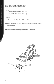
I -8 K-2 12 I -8) Tools: • Supplied Phillips Head Screwdriver 6-1 Align the Water Bottle Holder under the left side of the Seat Bottom. 6-2 Install and completely tighten the hardware. K-2) • Four M5x16 Screws (Ref. ASSEMBLY INSTRUCTIONS Step 6 Install Bottle Holder Parts: • Water Bottle Holder (Ref.
I -8 K-2 12 I -8) Tools: • Supplied Phillips Head Screwdriver 6-1 Align the Water Bottle Holder under the left side of the Seat Bottom. 6-2 Install and completely tighten the hardware. K-2) • Four M5x16 Screws (Ref. ASSEMBLY INSTRUCTIONS Step 6 Install Bottle Holder Parts: • Water Bottle Holder (Ref.
Assembly Manual
Page 17
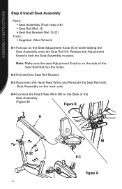
... Wrench 8-1 Pull out on the main unit. 8-4 Connect the Heart Rate Wire (M) to lock the Seat Assembly in place. ASSEMBLY INSTRUCTIONS Step 8 Install Seat Assembly Parts: • Seat Assembly (From step 3-6) • Seat Rail (Ref.
... Wrench 8-1 Pull out on the main unit. 8-4 Connect the Heart Rate Wire (M) to lock the Seat Assembly in place. ASSEMBLY INSTRUCTIONS Step 8 Install Seat Assembly Parts: • Seat Assembly (From step 3-6) • Seat Rail (Ref.
Assembly Manual
Page 18
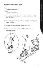
C Detail A C-2 C-1 15 ASSEMBLY INSTRUCTIONS Step 9 Install Handlebar Mast Parts: • Handlebar Mast (Ref C) Tools: • Supplied Allen Wrench 9-1 Remove the four Allen Bolts (C-1) and Curved Washers (C-2) from the frame . 9-2 Connect the Upper and Lower Computer Wires and Heart Rate Wires. (Detail A) 9-3 Insert the Handlebar Mast (C) into the main unit. 9-4 Re-install the four Allen Bolts and Curved Washers and completely tighten.
C Detail A C-2 C-1 15 ASSEMBLY INSTRUCTIONS Step 9 Install Handlebar Mast Parts: • Handlebar Mast (Ref C) Tools: • Supplied Allen Wrench 9-1 Remove the four Allen Bolts (C-1) and Curved Washers (C-2) from the frame . 9-2 Connect the Upper and Lower Computer Wires and Heart Rate Wires. (Detail A) 9-3 Insert the Handlebar Mast (C) into the main unit. 9-4 Re-install the four Allen Bolts and Curved Washers and completely tighten.
Assembly Manual
Page 19
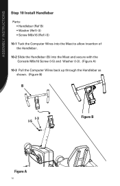
ASSEMBLY INSTRUCTIONS Step 10 Install Handlebar Parts: • Handlebar (Ref B) • Washer (Ref I-3) • Screw M8x16 (Ref I-5) 10-1 Tuck the Computer Wires into the Mast to allow insertion of the Handlebar . 10-2 Slide the Handlebar (B) into the Mast and secure with the Console M8x16 Screw (I-5) and Washer (I-3) . (Figure A) 10-3 Pull the Computer Wires back up through the Handlebar as shown. (Figure B) B I-3 I-5 Figure B Figure A 16
ASSEMBLY INSTRUCTIONS Step 10 Install Handlebar Parts: • Handlebar (Ref B) • Washer (Ref I-3) • Screw M8x16 (Ref I-5) 10-1 Tuck the Computer Wires into the Mast to allow insertion of the Handlebar . 10-2 Slide the Handlebar (B) into the Mast and secure with the Console M8x16 Screw (I-5) and Washer (I-3) . (Figure A) 10-3 Pull the Computer Wires back up through the Handlebar as shown. (Figure B) B I-3 I-5 Figure B Figure A 16
Assembly Manual
Page 20
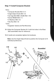
... (Ref. I -1) • 2 Washers (Ref. Note: Use the Angle Adjust Knob to position the Computer to fit individual preferences. ASSEMBLY INSTRUCTIONS Step 11 Install Computer Bracket Parts: • Computer Bracket (Ref.
... (Ref. I -1) • 2 Washers (Ref. Note: Use the Angle Adjust Knob to position the Computer to fit individual preferences. ASSEMBLY INSTRUCTIONS Step 11 Install Computer Bracket Parts: • Computer Bracket (Ref.


