
Service Manual
Page 1
...FLOW CHARTS 43-51 SCHEMATIC NOTES 52 IC, DIODE, AND TRANSISTOR PIN LAYOUTS 53 PC BOARD CONNECTIONS AND LOCATIONS 54 CAPACITOR AND RESISTOR CODE CHART 55 SCHEMATIC DIAGRAMS 56-57 Specifications POWER RATING 120VAC 120W (AVG.) ANTENNA INPUT IMPEDANCE 75Ω UHF/VHF/CATV DIGITAL RECEIVING CHANNEL...41.25MHz COLOR SUB CARRIEr 42.17MHz CABINET DIMENSIONS WIDTH 665.5mm HEIGHT 515.6mm DEPTH INCLUDING BASE 177.8mm © Sanyo Manufacturing Corporation 2008 DP26648, N6CE, PRODUCT CODE 113013904 REFERENCE No. You must refer to "Notices" to the Original Service Manual prior to servicing...
...FLOW CHARTS 43-51 SCHEMATIC NOTES 52 IC, DIODE, AND TRANSISTOR PIN LAYOUTS 53 PC BOARD CONNECTIONS AND LOCATIONS 54 CAPACITOR AND RESISTOR CODE CHART 55 SCHEMATIC DIAGRAMS 56-57 Specifications POWER RATING 120VAC 120W (AVG.) ANTENNA INPUT IMPEDANCE 75Ω UHF/VHF/CATV DIGITAL RECEIVING CHANNEL...41.25MHz COLOR SUB CARRIEr 42.17MHz CABINET DIMENSIONS WIDTH 665.5mm HEIGHT 515.6mm DEPTH INCLUDING BASE 177.8mm © Sanyo Manufacturing Corporation 2008 DP26648, N6CE, PRODUCT CODE 113013904 REFERENCE No. You must refer to "Notices" to the Original Service Manual prior to servicing...
Service Manual
Page 5
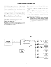
...off within three seconds. Inverter Power Board Main IC800 (CPU) K8B 1 Power On 18 32 Power Fail Q810/Q811 23 Power Fail (LVDS) D1683 IC1680 2 5V LVDS D1621 D1653 D6053 D1620 5 Q1610 6 3.3V 8 IC1651 6.5V D6052 6 IC6050 3.3V D1671 5 IC1671 9V D1662 6 IC1661 5V D1679 9 IC001 10V -5- POWER FAILURE CIRCUIT CPU (IC800) ... function included in the CPU which checks for the proper voltage supplies. 4. Check all circuits shown below . 3. Press the Power key and check for an abnormal condition in 15 minutes, the set will go to standby mode when there is circuit failure as...
...off within three seconds. Inverter Power Board Main IC800 (CPU) K8B 1 Power On 18 32 Power Fail Q810/Q811 23 Power Fail (LVDS) D1683 IC1680 2 5V LVDS D1621 D1653 D6053 D1620 5 Q1610 6 3.3V 8 IC1651 6.5V D6052 6 IC6050 3.3V D1671 5 IC1671 9V D1662 6 IC1661 5V D1679 9 IC001 10V -5- POWER FAILURE CIRCUIT CPU (IC800) ... function included in the CPU which checks for the proper voltage supplies. 4. Check all circuits shown below . 3. Press the Power key and check for an abnormal condition in 15 minutes, the set will go to standby mode when there is circuit failure as...
Service Manual
Page 7
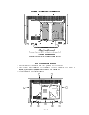
Lift the LCD panel from LCD panel, speakers, and control board. 2. Once you have taken off the Lid back, stand base, power unit and main board remove 9 screws (C:3X14) and 4 screws (D:4X8) to take the back cabinet off LCD panel removal Removal 1. Disconnect the lead wires from the front cabinet. -7- POWER AND MAIN BOARD REMOVAL 1: Main Board Removal Remove 5 screws (3X14) to take the main board off. 2: Power Unit Removal Remove 6 screws (3X14) to take the power unit off . 3.
Lift the LCD panel from LCD panel, speakers, and control board. 2. Once you have taken off the Lid back, stand base, power unit and main board remove 9 screws (C:3X14) and 4 screws (D:4X8) to take the back cabinet off LCD panel removal Removal 1. Disconnect the lead wires from the front cabinet. -7- POWER AND MAIN BOARD REMOVAL 1: Main Board Removal Remove 5 screws (3X14) to take the main board off. 2: Power Unit Removal Remove 6 screws (3X14) to take the power unit off . 3.
Service Manual
Page 41
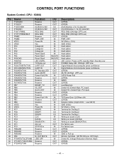
... 6 7 8 9 10 11 12 13 14 15 16 17 18 19 20 21 22 23 24 25 26 27 28 29 30 31 32 33 34 35 36 37 38 39 40 41 42 43 44 45 46 47...0Vdc) Hard option Hard option Hard option Hard option Hard option Hard option LED control Power on/PC standby:High, Standby:Low POWER Relay SW ON:High OFF:Low Digital Module microcomputer piece confidence Digital Module microcomputer piece ... TV Power Error (L)/Others (H) (OPEN) Solution Option (High:US1H Low:US1F) GND (0Vdc) 5V (5Vdc ± 10%) Terminal for De-Bug 3 Terminal for De-Bug 2 Terminal for De-Bug 1 Writing on board (CLK) Writing on board (DATA0) Writing on board ...
... 6 7 8 9 10 11 12 13 14 15 16 17 18 19 20 21 22 23 24 25 26 27 28 29 30 31 32 33 34 35 36 37 38 39 40 41 42 43 44 45 46 47...0Vdc) Hard option Hard option Hard option Hard option Hard option Hard option LED control Power on/PC standby:High, Standby:Low POWER Relay SW ON:High OFF:Low Digital Module microcomputer piece confidence Digital Module microcomputer piece ... TV Power Error (L)/Others (H) (OPEN) Solution Option (High:US1H Low:US1F) GND (0Vdc) 5V (5Vdc ± 10%) Terminal for De-Bug 3 Terminal for De-Bug 2 Terminal for De-Bug 1 Writing on board (CLK) Writing on board (DATA0) Writing on board ...
Service Manual
Page 54
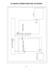
CN903 K8L PC BOARD CONNECTIONS AND LOCATIONS - 54 - LCD PANEL EL901 SPEAKER 2 2 1 1 KSP K8B CN902 POWER UNIT U901 MAIN UNIT K8FRA K5LV CONTROL UNIT 1 5V_STBY 2 GND 3 KEY_IN 4 RC_IN 5 LED_ON GND 6 FROM MAIN UNIT(K8FRA) CN1 K8PC PC UNIT
CN903 K8L PC BOARD CONNECTIONS AND LOCATIONS - 54 - LCD PANEL EL901 SPEAKER 2 2 1 1 KSP K8B CN902 POWER UNIT U901 MAIN UNIT K8FRA K5LV CONTROL UNIT 1 5V_STBY 2 GND 3 KEY_IN 4 RC_IN 5 LED_ON GND 6 FROM MAIN UNIT(K8FRA) CN1 K8PC PC UNIT


