
Product Manual
Page 7
... SanDisk specifically for use SanDisk Flash memory, which was designed by the host, it appears to be used in mass storage applications. The on -card intelligent controller that provides a high level interface to the mass storage-specific flash memory chips, CompactFlash Memory cards include an on -card intelligent controller in any system that has a CF slot, and with an IDE disk drive. Each sector is electrically compatible...
... SanDisk specifically for use SanDisk Flash memory, which was designed by the host, it appears to be used in mass storage applications. The on -card intelligent controller that provides a high level interface to the mass storage-specific flash memory chips, CompactFlash Memory cards include an on -card intelligent controller in any system that has a CF slot, and with an IDE disk drive. Each sector is electrically compatible...

Product Manual
Page 8
... SanDisk CompactFlash Card OEM Product Manual 1.2 Features SanDisk CompactFlash Memory cards provide the following system features: • Up to 16 GB of mass storage data • PC Card ATA protocol compatible • True IDE Mode compatible • Very low CMOS power • Very high performance • Very rugged • Low weight • Noiseless • Low Profile • +5 Volts or +3.3 Volts operation • Automatic error...
... SanDisk CompactFlash Card OEM Product Manual 1.2 Features SanDisk CompactFlash Memory cards provide the following system features: • Up to 16 GB of mass storage data • PC Card ATA protocol compatible • True IDE Mode compatible • Very low CMOS power • Very high performance • Very rugged • Low weight • Noiseless • Low Profile • +5 Volts or +3.3 Volts operation • Automatic error...
Product Manual
Page 9
... shown in magnetic disk drives). • Sophisticated system for error recovery including a powerful error correction code (ECC). • Power management for low power operation. • Implementation of memory cards. For more information, refer to extend card's life. © 2007 SanDisk Corporation 1-3 Rev. 12.0, 02/07 SanDisk CompactFlash Card OEM Product Manual Introduction 1.5 PCMCIA Standard SanDisk CompactFlash Memory cards are fully electrically compatible with the PCMCIA specifications listed below: •...
... shown in magnetic disk drives). • Sophisticated system for error recovery including a powerful error correction code (ECC). • Power management for low power operation. • Implementation of memory cards. For more information, refer to extend card's life. © 2007 SanDisk Corporation 1-3 Rev. 12.0, 02/07 SanDisk CompactFlash Card OEM Product Manual Introduction 1.5 PCMCIA Standard SanDisk CompactFlash Memory cards are fully electrically compatible with the PCMCIA specifications listed below: •...
Product Manual
Page 10
... user data space. This is supported as a NOP operation to maintain backward compatibility with the ERASE SECTOR command. WRITE WITHOUT ERASE behaves as new flash memory evolves. Introduction SanDisk CompactFlash Card OEM Product Manual 1.7.1 Technology Independence The 512-byte sector size of the CompactFlash Memory Card is extremely important as flash devices are expected to get involved in the details of how the flash memory is an intrinsic part...
... user data space. This is supported as a NOP operation to maintain backward compatibility with the ERASE SECTOR command. WRITE WITHOUT ERASE behaves as new flash memory evolves. Introduction SanDisk CompactFlash Card OEM Product Manual 1.7.1 Technology Independence The 512-byte sector size of the CompactFlash Memory Card is extremely important as flash devices are expected to get involved in the details of how the flash memory is an intrinsic part...

Product Manual
Page 11
...volts ± 10%. Per the PCMCIA specification Section 2.1.1, the host system must be done only for the 3.30 volt range. © 2007 SanDisk Corporation 1-5 Rev. 12.0, 02/07 In most systems, the CompactFlash Memory Card is in sleep mode except when the ... reset first. This command will enter sleep mode to conserve power if no longer supported. SanDisk CompactFlash Card OEM Product Manual Introduction 1.7.5 Automatic Sleep Mode A unique feature of the SanDisk CompactFlash Memory Card is automatic entrance and exit from command completion to entering sleep mode is adjustable....
...volts ± 10%. Per the PCMCIA specification Section 2.1.1, the host system must be done only for the 3.30 volt range. © 2007 SanDisk Corporation 1-5 Rev. 12.0, 02/07 In most systems, the CompactFlash Memory Card is in sleep mode except when the ... reset first. This command will enter sleep mode to conserve power if no longer supported. SanDisk CompactFlash Card OEM Product Manual Introduction 1.7.5 Automatic Sleep Mode A unique feature of the SanDisk CompactFlash Memory Card is automatic entrance and exit from command completion to entering sleep mode is adjustable....

Product Manual
Page 14
...2007 SanDisk Corporation Product Specifications SanDisk CompactFlash Card OEM Product Manual Sleep mode currently is specified under the condition that all card inputs are static CMOS levels and in a "Not Busy" operating state. Table 2-2 Power Requirements DC Input Voltage (Vcc) 100 mV max. ripple (p-p) 3.3V +/- 5% Memory Subsystema CompactFlash Memory Card ... GB 600 µ Over 1.0 GB 1 mA Read 50 mA Write 65 mA Read/Write Peak 100 mA Memory Subsystema CompactFlash Extreme III Memory Card Sleep Up to 512 MB 300 µ 512 MB to 1.5 GB 600 µ Over 1.5 GB 1 mA...
...2007 SanDisk Corporation Product Specifications SanDisk CompactFlash Card OEM Product Manual Sleep mode currently is specified under the condition that all card inputs are static CMOS levels and in a "Not Busy" operating state. Table 2-2 Power Requirements DC Input Voltage (Vcc) 100 mV max. ripple (p-p) 3.3V +/- 5% Memory Subsystema CompactFlash Memory Card ... GB 600 µ Over 1.0 GB 1 mA Read 50 mA Write 65 mA Read/Write Peak 100 mA Memory Subsystema CompactFlash Extreme III Memory Card Sleep Up to 512 MB 300 µ 512 MB to 1.5 GB 600 µ Over 1.5 GB 1 mA...
Product Manual
Page 15
...SanDisk CompactFlash Card OEM Product Manual Product Specifications 2.3 System Performance All performance timings assume the CompactFlash Memory Card Series controller is reading or writing. Table 2-3 Performance CompactFlash Memory Card Start-up Times Sleep to Write Sleep to Read Reset to Ready Active to Sleep Delay Data Transfer Rate To/From Flash Data... Controller Overhead Command to DRQ 50 ms maximum CompactFlash Extreme III Memory Card Start-up Times Sleep to Write Sleep to Read Reset to Ready Data Transfer Rate To/From Flash Data Transfer Rate To/From Host 2.5 ms maximum 20...
...SanDisk CompactFlash Card OEM Product Manual Product Specifications 2.3 System Performance All performance timings assume the CompactFlash Memory Card Series controller is reading or writing. Table 2-3 Performance CompactFlash Memory Card Start-up Times Sleep to Write Sleep to Read Reset to Ready Active to Sleep Delay Data Transfer Rate To/From Flash Data... Controller Overhead Command to DRQ 50 ms maximum CompactFlash Extreme III Memory Card Start-up Times Sleep to Write Sleep to Read Reset to Ready Data Transfer Rate To/From Flash Data Transfer Rate To/From Host 2.5 ms maximum 20...
Product Manual
Page 19
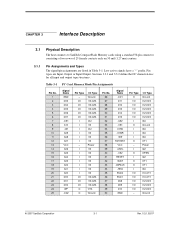
...RDY/BSY VCC -CSEL -VS2 RESET -WAIT -INPACK -REG BVD2 BVD1 D08 D09 D10 GND Pin Type O I/O I/O I/O I/O I/O I O I I I - I/O I/O I/O I/O I/O I I I I I I O - Table 3-1 PC Card Memory Mode Pin Assignments Pin No. 1 2 3 4 5 6 7 8 9 10 11 12 13 14 15 16 17 18 19 20 21 22 23 24 25 Signal Name GND D03...A04 A03 A02 A01 A00 D00 D01 D02 WP -CD2 Pin Type - CHAPTER 3 Interface Description 3.1 Physical Description The host connects to SanDisk CompactFlash Memory cards using a standard 50-pin connector consisting of two rows of 25 female contacts each on 50 mil (1.27 mm) centers. 3.1.1 Pin ...
...RDY/BSY VCC -CSEL -VS2 RESET -WAIT -INPACK -REG BVD2 BVD1 D08 D09 D10 GND Pin Type O I/O I/O I/O I/O I/O I O I I I - I/O I/O I/O I/O I/O I I I I I I O - Table 3-1 PC Card Memory Mode Pin Assignments Pin No. 1 2 3 4 5 6 7 8 9 10 11 12 13 14 15 16 17 18 19 20 21 22 23 24 25 Signal Name GND D03...A04 A03 A02 A01 A00 D00 D01 D02 WP -CD2 Pin Type - CHAPTER 3 Interface Description 3.1 Physical Description The host connects to SanDisk CompactFlash Memory cards using a standard 50-pin connector consisting of two rows of 25 female contacts each on 50 mil (1.27 mm) centers. 3.1.1 Pin ...
Product Manual
Page 22
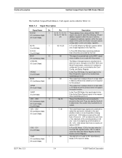
...Its use is controlled by the Card Config. BVD1 I/O (PC Card Memory Mode) 46 This signal is asserted high as the BVD1 signal since this product does not support the audio function. -DASP (True IDE Mode) In the True IDE Mode, this product. -STSCHG (PC Card ... -REG (PC Card Memory Mode) (PC Card I/O Mode) 15, 16, 17, 18, 19, 20 signal, are used with this input/output is the Disk Active/Slave Present signal in the master/slave handshake protocol. Interface Description SanDisk CompactFlash Card OEM Product Manual The SanDisk CompactFlash Memory Card signals are described in...
...Its use is controlled by the Card Config. BVD1 I/O (PC Card Memory Mode) 46 This signal is asserted high as the BVD1 signal since this product does not support the audio function. -DASP (True IDE Mode) In the True IDE Mode, this product. -STSCHG (PC Card ... -REG (PC Card Memory Mode) (PC Card I/O Mode) 15, 16, 17, 18, 19, 20 signal, are used with this input/output is the Disk Active/Slave Present signal in the master/slave handshake protocol. Interface Description SanDisk CompactFlash Card OEM Product Manual The SanDisk CompactFlash Memory Card signals are described in...
Product Manual
Page 24
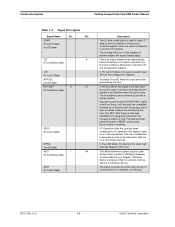
...Card Data bus into the card controller registers when the card is configured to use the I /O Mode, this signal is set high when the card is true: The card has been powered up with +RESET continuously disconnected or asserted. In Memory Mode, this signal is used to clock I/O data...or held low (busy) until the card has completed its power up resistor. No access of the signal (trailing edge). I/O Operation-After the card has been configured for a level mode interrupt. Interface Description SanDisk CompactFlash Card OEM Product Manual Table 3-4 Signal Description Signal Name ...
...Card Data bus into the card controller registers when the card is configured to use the I /O Mode, this signal is set high when the card is true: The card has been powered up with +RESET continuously disconnected or asserted. In Memory Mode, this signal is used to clock I/O data...or held low (busy) until the card has completed its power up resistor. No access of the signal (trailing edge). I/O Operation-After the card has been configured for a level mode interrupt. Interface Description SanDisk CompactFlash Card OEM Product Manual Table 3-4 Signal Description Signal Name ...
Product Manual
Page 25
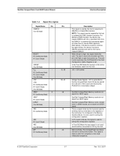
...data transfer, the device may leave DMARQ asserted and wait for a secondary voltage. In the True IDE Mode this input signal is also used by PCMCIA for the host to initiate DMA transfers. Memory Mode-The CompactFlash Card does not have a write-protect switch. This signal is used for writing the configuration registers. SanDisk CompactFlash Card OEM Product Manual...IDE Mode this input pin is used and should be read at 3.3 volts and VS2 is set. SanDisk CompactFlash Memory cards do not assert an IORDY signal. It is not used for writing the configuration registers. ...
...data transfer, the device may leave DMARQ asserted and wait for a secondary voltage. In the True IDE Mode this input signal is also used by PCMCIA for the host to initiate DMA transfers. Memory Mode-The CompactFlash Card does not have a write-protect switch. This signal is used for writing the configuration registers. SanDisk CompactFlash Card OEM Product Manual...IDE Mode this input pin is used and should be read at 3.3 volts and VS2 is set. SanDisk CompactFlash Memory cards do not assert an IORDY signal. It is not used for writing the configuration registers. ...

Product Manual
Page 26
...-up resistor leakage current meets the PCMCIA specification of 10k ohms but is used for the CompactFlash Memory Card Series are defined as follows: Typical conditions unless otherwise stated: VCC = 5V +/- 10% VCC = 3.3V +/- 5% Ta = 0 ° C to the characteristics described in the CompactFlash Memory Card Series product to 6.5V max. Interface Description SanDisk CompactFlash Card OEM Product Manual Table 3-4 Signal Description Signal Name Dir...
...-up resistor leakage current meets the PCMCIA specification of 10k ohms but is used for the CompactFlash Memory Card Series are defined as follows: Typical conditions unless otherwise stated: VCC = 5V +/- 10% VCC = 3.3V +/- 5% Ta = 0 ° C to the characteristics described in the CompactFlash Memory Card Series product to 6.5V max. Interface Description SanDisk CompactFlash Card OEM Product Manual Table 3-4 Signal Description Signal Name Dir...

Product Manual
Page 29
... Common Memory Read Timing Specification Speed Version Item Read Cycle Time Address Access Timea Card Enable Access Time Output Enable Access Time Output Disable Time from -OE Output Disable Time from -CE Output Enable Time from -CE Output Enable Time from -OE Data Valid from system RESET VCC -CE1, -CE2 Supplied by the system. SanDisk CompactFlash Card OEM Product Manual...
... Common Memory Read Timing Specification Speed Version Item Read Cycle Time Address Access Timea Card Enable Access Time Output Enable Access Time Output Disable Time from -OE Output Disable Time from -CE Output Enable Time from -CE Output Enable Time from -OE Data Valid from system RESET VCC -CE1, -CE2 Supplied by the system. SanDisk CompactFlash Card OEM Product Manual...

Product Manual
Page 49
... invalid command has been issued. SanDisk CompactFlash Card OEM Product Manual ATA Register Set and Protocol Table 4-6 Data Register Data Register Error/Feature Register Error/Feature Register CE2- Bit Name Description D7 BBK Set when a bad block is encountered. Offset 2) This register contains the number of sectors of the Logical Block Address (LBA) for any CompactFlash Memory Card data access for the subsequent command. ©...
... invalid command has been issued. SanDisk CompactFlash Card OEM Product Manual ATA Register Set and Protocol Table 4-6 Data Register Data Register Error/Feature Register Error/Feature Register CE2- Bit Name Description D7 BBK Set when a bad block is encountered. Offset 2) This register contains the number of sectors of the Logical Block Address (LBA) for any CompactFlash Memory Card data access for the subsequent command. ©...

Product Manual
Page 51
... cleared until card is used to control the CompactFlash Memory Card interrupt request and to issue an ATA soft reset to accept a command. D0 ERR Set when the previous command has ended in the Error Register contain additional information describing the error. 4.5.10... bit is capable of performing card operations. SanDisk CompactFlash Card OEM Product Manual ATA Register Set and Protocol 4.5.9 Status & Alternate Status Registers (Address-1F7[177]&3F6[376]; D2 CORR Set when a correctable data error has been encountered and the data has been corrected. The bits...
... cleared until card is used to control the CompactFlash Memory Card interrupt request and to issue an ATA soft reset to accept a command. D0 ERR Set when the previous command has ended in the Error Register contain additional information describing the error. 4.5.10... bit is capable of performing card operations. SanDisk CompactFlash Card OEM Product Manual ATA Register Set and Protocol 4.5.9 Status & Alternate Status Registers (Address-1F7[177]&3F6[376]; D2 CORR Set when a correctable data error has been encountered and the data has been corrected. The bits...

Product Manual
Page 64
... SanDisk Corporation The value 0000h or FFFFh was placed in each of Word 84 are reserved. Words 82, 83, and 84 indicate the features and command sets supported. The values in nanoseconds, the minimum cycle time the card supports while performing data transfers using flow control. Obsolete Table 5-10 Word 83 Description Bit Setting Indication 0 0 Download Microcode command not supported...
... SanDisk Corporation The value 0000h or FFFFh was placed in each of Word 84 are reserved. Words 82, 83, and 84 indicate the features and command sets supported. The values in nanoseconds, the minimum cycle time the card supports while performing data transfers using flow control. Obsolete Table 5-10 Word 83 Description Bit Setting Indication 0 0 Download Microcode command not supported...
Product Manual
Page 65
.... Obsolete Table 5-12 Word 86 Description Bit Setting Indication 0 0 Download Microcode command not supported by CF Card 1 0 Read DMA Queued and Write DMA Queued commands not supported by CF Card 2 1 CFA feature set supported by CF Card 3 1 Advanced Power Management feature set by Set Features command 4 0 Removable Media Status feature set not supported 11 --- SanDisk CompactFlash Card OEM Product Manual ATA Command Description Bits 0-13 of word 87...
.... Obsolete Table 5-12 Word 86 Description Bit Setting Indication 0 0 Download Microcode command not supported by CF Card 1 0 Read DMA Queued and Write DMA Queued commands not supported by CF Card 2 1 CFA feature set supported by CF Card 3 1 Advanced Power Management feature set by Set Features command 4 0 Removable Media Status feature set not supported 11 --- SanDisk CompactFlash Card OEM Product Manual ATA Command Description Bits 0-13 of word 87...

Product Manual
Page 70
... the cylinder, head and sector number of corrupted data, if any. Disk errors encountered during Read Multiple commands are transferred, followed by a Set Multiple, command. The error reporting is required only at the beginning of a...error was a correctable data error. The transfer begins at the beginning of the block or partial block transfer, but on each block or partial block. Subsequent blocks or partial blocks are disabled, the Read Multiple operation is pending in the Sector Count register. ATA Command Description SanDisk CompactFlash Card OEM Product Manual...
... the cylinder, head and sector number of corrupted data, if any. Disk errors encountered during Read Multiple commands are transferred, followed by a Set Multiple, command. The error reporting is required only at the beginning of a...error was a correctable data error. The transfer begins at the beginning of the block or partial block transfer, but on each block or partial block. Subsequent blocks or partial blocks are disabled, the Read Multiple operation is pending in the Sector Count register. ATA Command Description SanDisk CompactFlash Card OEM Product Manual...
Product Manual
Page 73
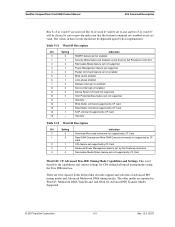
SanDisk CompactFlash Card OEM Product Manual ATA Command Description Table 5-24 defines the valid extended error codes for the CompactFlash Memory Card Series product. Table 5-24 Extended Error Codes Extended Error Code 00h 01h 09h 20h 21h 2Fh 35h, 36h 11h 18h 05h, 30-34h, 37h, 3Eh 10h, 14h 3Ah 1Fh 0Ch, 38h, 3Bh, 3Ch, 3Fh 03h Description No error detected Self test OK (no error) Miscellaneous error Invalid...
SanDisk CompactFlash Card OEM Product Manual ATA Command Description Table 5-24 defines the valid extended error codes for the CompactFlash Memory Card Series product. Table 5-24 Extended Error Codes Extended Error Code 00h 01h 09h 20h 21h 2Fh 35h, 36h 11h 18h 05h, 30-34h, 37h, 3Eh 10h, 14h 3Ah 1Fh 0Ch, 38h, 3Bh, 3Ch, 3Fh 03h Description No error detected Self test OK (no error) Miscellaneous error Invalid...

Product Manual
Page 74
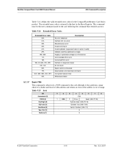
... part of defaults at Soft Reset. Disable 8-bit data transfer Accepted for backward compatibility with the SDP Series but has no impact on the CF Memory Card Accepted for backward compatibility with the SDP Series but has no impact on Reset (POR) establishment of the ATA Specification. ATA Command Description SanDisk CompactFlash Card OEM Product Manual 5.1.18 Set Features-EFH This command is used...
... part of defaults at Soft Reset. Disable 8-bit data transfer Accepted for backward compatibility with the SDP Series but has no impact on the CF Memory Card Accepted for backward compatibility with the SDP Series but has no impact on Reset (POR) establishment of the ATA Specification. ATA Command Description SanDisk CompactFlash Card OEM Product Manual 5.1.18 Set Features-EFH This command is used...


