Installation Instructions
Page 9
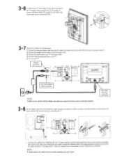
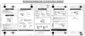
3.6 To prevent your TV from the EX-LINK on the Wall mount to the EX-LINK (Service) on the angle adjustment device and let it bind the cables as shown in the figure below . 0 Connect the communications cable from falling, fix ... that the adapter and cables are connected to recheck that they do not 8 come undone while you are too taut when operating your wall mount. O J , EX-LINK (Service) connector Make sure to their correct connecting locations. 3 - Check the operation two or three times to your TV. 0 Tu n on your TV when rotating...
3.6 To prevent your TV from the EX-LINK on the Wall mount to the EX-LINK (Service) on the angle adjustment device and let it bind the cables as shown in the figure below . 0 Connect the communications cable from falling, fix ... that the adapter and cables are connected to recheck that they do not 8 come undone while you are too taut when operating your wall mount. O J , EX-LINK (Service) connector Make sure to their correct connecting locations. 3 - Check the operation two or three times to your TV. 0 Tu n on your TV when rotating...
Installation Instructions
Page 13
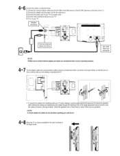
... . 0 Connect the communications cable from the EX-LINK on the Wall mount to their correct connecting locations. 4 - Adapter connector \\ II4 C )SEr UP ®)0012V 0 0 0 0 moo )EX-UXE = 0 0 LJ Communications cable connector EX-LINK (Service) connector GIC)7 * Make sure to... recheck that they do not come undone while you are connected to the EX-LINK (Service) on your wall mount. 8 4 - 4 - 6 Connect the ...
... . 0 Connect the communications cable from the EX-LINK on the Wall mount to their correct connecting locations. 4 - Adapter connector \\ II4 C )SEr UP ®)0012V 0 0 0 0 moo )EX-UXE = 0 0 LJ Communications cable connector EX-LINK (Service) connector GIC)7 * Make sure to... recheck that they do not come undone while you are connected to the EX-LINK (Service) on your wall mount. 8 4 - 4 - 6 Connect the ...
Installation Instructions
Page 32
... for more than 45° forwards when fastening the screws. Contact your TV Manual. Refer to the Installation Manual for Samsung 40" to ensure that hold the wall mount holding bars in place. 3.Remove the rwo wall mount holding bars. Attach...& left . 10.0 4-3. Lower it may be released when a screw is removed. 2. Cable Connections and Setup 5-1. Adapter connector 0 fi Communications cable connector a U EX-LINK (Service) connector X Note 1. Press the Setup button. X Note: To operate, refer to the Installation Manual.) X Note: First check the color of the wall. ...
... for more than 45° forwards when fastening the screws. Contact your TV Manual. Refer to the Installation Manual for Samsung 40" to ensure that hold the wall mount holding bars in place. 3.Remove the rwo wall mount holding bars. Attach...& left . 10.0 4-3. Lower it may be released when a screw is removed. 2. Cable Connections and Setup 5-1. Adapter connector 0 fi Communications cable connector a U EX-LINK (Service) connector X Note 1. Press the Setup button. X Note: To operate, refer to the Installation Manual.) X Note: First check the color of the wall. ...
Installation Instructions
Page 35
... sure to the screws. TV manual) 3.Engage the TV hanger.(Use M8X25.) U 0 0 0 0 Note: Refer to the Installation Manual to locate the position for Samsung 40" to fasten the screws for more than 45° forwards when fastening the screws. Insert the communications cable securely. Installation CD O TT TT T g 11...installation wall and check the installation location and check the level using the housing and three screws.(optional) Adapter installation location 0 0 • • = 0 0 ( I ' 0 0 EX-LINK (Service) connector X Note 1. Check the cable connections.
... sure to the screws. TV manual) 3.Engage the TV hanger.(Use M8X25.) U 0 0 0 0 Note: Refer to the Installation Manual to locate the position for Samsung 40" to fasten the screws for more than 45° forwards when fastening the screws. Insert the communications cable securely. Installation CD O TT TT T g 11...installation wall and check the installation location and check the level using the housing and three screws.(optional) Adapter installation location 0 0 • • = 0 0 ( I ' 0 0 EX-LINK (Service) connector X Note 1. Check the cable connections.
