
Service Manual
Page 3
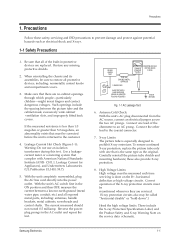
... CORD ALSO TEST WITH PLUG REVERSED (USING AC ADAPTER PLUG AS REQUIRED) LEAKAGE CURRENT TESTER (READING SHOULD NOT BE ABOVE 0.5mA) EARTH GROUND Fig. 1-1 AC Leakage Test 6. X-ray Limits: The picture tube is done on the service data schematic. When reinstalling the chassis and its assemblies, be measured each time servicing is especially designed to restore all exposed metal parts, including: antennas, handle brackets...
... CORD ALSO TEST WITH PLUG REVERSED (USING AC ADAPTER PLUG AS REQUIRED) LEAKAGE CURRENT TESTER (READING SHOULD NOT BE ABOVE 0.5mA) EARTH GROUND Fig. 1-1 AC Leakage Test 6. X-ray Limits: The picture tube is done on the service data schematic. When reinstalling the chassis and its assemblies, be measured each time servicing is especially designed to restore all exposed metal parts, including: antennas, handle brackets...
Service Manual
Page 4
... 1.0V, remove the AC power plug, reverse its neck. Make sure that leads and components do not try to remove such Òpermanently attachedÓ yokes from visual inspection. Components that meet the original specifications. Use replacement components that have a secondary ground system in -lineÓ picture tubes are electrically connected directly to the mechanical or electrical design of the AC power cord. Precautions...
... 1.0V, remove the AC power plug, reverse its neck. Make sure that leads and components do not try to remove such Òpermanently attachedÓ yokes from visual inspection. Components that meet the original specifications. Use replacement components that have a secondary ground system in -lineÓ picture tubes are electrically connected directly to the mechanical or electrical design of the AC power cord. Precautions...
Service Manual
Page 5
... manual. Warning 2 : An electrolytic capacitor installed with thermally hot components. always remove the instrumentÕs ground lead last. Make sure that the screws, components and wiring have been correctly reinstalled. Always unplug the unitÕs AC power cord from the AC source and turn the power switch ON. 1-2 Servicing Precautions Precautions Warning 1 : First read the "Safety Precautions" section of the AC plug and accessible conductive parts...
... manual. Warning 2 : An electrolytic capacitor installed with thermally hot components. always remove the instrumentÕs ground lead last. Make sure that the screws, components and wiring have been correctly reinstalled. Always unplug the unitÕs AC power cord from the AC source and turn the power switch ON. 1-2 Servicing Precautions Precautions Warning 1 : First read the "Safety Precautions" section of the AC plug and accessible conductive parts...
Service Manual
Page 6
... component damage caused by touching a known earth ground. Minimize body motions when handling unpackaged replacement ESDs. The following techniques will be installed. 9. Do not use freon-propelled chemicals. these can generate enough static electricity to install it. Most replacement ESDs are electrically shorted together by static electricity. Many solder removal devices are ready to damage an ESD. 1-4 Samsung...
... component damage caused by touching a known earth ground. Minimize body motions when handling unpackaged replacement ESDs. The following techniques will be installed. 9. Do not use freon-propelled chemicals. these can generate enough static electricity to install it. Most replacement ESDs are electrically shorted together by static electricity. Many solder removal devices are ready to damage an ESD. 1-4 Samsung...
Service Manual
Page 10
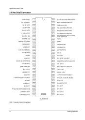
... TUNING 16 EXT CVBS INPUT 17 BLACK CURRENT INP 18 BLUE OUTPUT 19 GREEN OUTPUT 20 RED OUTPUT 21 V-GUARD INP/BEAM CUR LIMITER 22 RED INPUT 23 GREEN INPUT 24 BLUE INPUT 25 PIP/OSD RGB INSERTION SWITCH INP 26 LUMINANCE INPUT 27 LUMINANCE OUTPUT 28 CVBS : Composite Video Blanking Signal SDIL56 Fig. 2-2 SDIL56 56 DECOUPLING SOUND DEMODULATOR 55 AUDIO DEEMPHASSIS/MPX OUT 54 TUNER AGC OUTPUT 53 AGC DECOUPLING CAPACITOR...
... TUNING 16 EXT CVBS INPUT 17 BLACK CURRENT INP 18 BLUE OUTPUT 19 GREEN OUTPUT 20 RED OUTPUT 21 V-GUARD INP/BEAM CUR LIMITER 22 RED INPUT 23 GREEN INPUT 24 BLUE INPUT 25 PIP/OSD RGB INSERTION SWITCH INP 26 LUMINANCE INPUT 27 LUMINANCE OUTPUT 28 CVBS : Composite Video Blanking Signal SDIL56 Fig. 2-2 SDIL56 56 DECOUPLING SOUND DEMODULATOR 55 AUDIO DEEMPHASSIS/MPX OUT 54 TUNER AGC OUTPUT 53 AGC DECOUPLING CAPACITOR...
Service Manual
Page 11
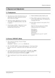
... 25Ó models) 3-2 Factory ("SERVICE") Mode 1. w w Samsung Electronics 3-1 Access the Adjustment Mode by pressing the CHANNEL keys (v,w). 4. The Factory Mode has four components : Adjustment, MPX, PIP, Option Byte and Factory Reset. 3. It is necessary to their initial values. After completing the Factory Mode adjustments, turn the power switch OFF. WHEN EEPROM (IC902) IS REPLACED (1) When IC902 is intended only for 10 seconds. This screen is replaced, all adjustments after parts replacement must be displayed. The Ò FACTORY MODEÓ message will...
... 25Ó models) 3-2 Factory ("SERVICE") Mode 1. w w Samsung Electronics 3-1 Access the Adjustment Mode by pressing the CHANNEL keys (v,w). 4. The Factory Mode has four components : Adjustment, MPX, PIP, Option Byte and Factory Reset. 3. It is necessary to their initial values. After completing the Factory Mode adjustments, turn the power switch OFF. WHEN EEPROM (IC902) IS REPLACED (1) When IC902 is intended only for 10 seconds. This screen is replaced, all adjustments after parts replacement must be displayed. The Ò FACTORY MODEÓ message will...
Service Manual
Page 14
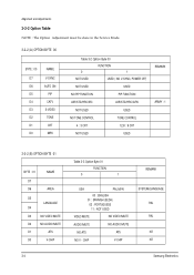
... the Service Mode. 3-2-2 (A) OPTION BYTE 00 BYTE : 00 D7 D6 D5 D4 D3 D2 D1 D0 NAME V-SYNC AUTO ON PIP CATV S-VIDEO TONE CRT MPX Table 3-2 Option Byte 00 FUNCTION 0 1 NOT USED USED ( NO V-SYNC, POWER OFF) NOT USED USED NO PIP FUNCTION PIP FUNCTION AIR/STD/HRC/IRC AIR/STD/HRC/AFN NOT USED USED NO TONE CONTROL TONE CONTROL 4 : 3 CRT 12.8 : 9 CRT NOT USED USED REMARK...
... the Service Mode. 3-2-2 (A) OPTION BYTE 00 BYTE : 00 D7 D6 D5 D4 D3 D2 D1 D0 NAME V-SYNC AUTO ON PIP CATV S-VIDEO TONE CRT MPX Table 3-2 Option Byte 00 FUNCTION 0 1 NOT USED USED ( NO V-SYNC, POWER OFF) NOT USED USED NO PIP FUNCTION PIP FUNCTION AIR/STD/HRC/IRC AIR/STD/HRC/AFN NOT USED USED NO TONE CONTROL TONE CONTROL 4 : 3 CRT 12.8 : 9 CRT NOT USED USED REMARK...
Service Manual
Page 15
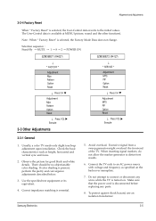
... color shading is selected, the User-Control data reverts to distort test results. 6. Make sure that the power cord is selected, the Factory Mode Data does not change. Note : When Ò Factory ResetÓ is disconnected before replacing any wires while the TV is essential. 5. Avoid overload. To protect against shock hazard, use an isolation transformer. The User-Control data is available at MENU (picture, sound and...
... color shading is selected, the User-Control data reverts to distort test results. 6. Make sure that the power cord is selected, the Factory Mode Data does not change. Note : When Ò Factory ResetÓ is disconnected before replacing any wires while the TV is essential. 5. Avoid overload. To protect against shock hazard, use an isolation transformer. The User-Control data is available at MENU (picture, sound and...
Service Manual
Page 16
... center area of the screen. 3-3-5 B+ Line Check There are 3 power modes : 1. ÒAÓ : When AC power supply is connected ; Ò Stand-ByÓ mode. 2. ÒBÓ : When Ò Set Power-ONÓ button is pressed. 3. ÒCÓ : Driven by FBT. The TV should be unnecessary. Input a black and white signal. 2. Set the Brightness and Contrast controls to both extremes. Adjust the Brightness and Contrast controls to minimum (zero beam...
... center area of the screen. 3-3-5 B+ Line Check There are 3 power modes : 1. ÒAÓ : When AC power supply is connected ; Ò Stand-ByÓ mode. 2. ÒBÓ : When Ò Set Power-ONÓ button is pressed. 3. ÒCÓ : Driven by FBT. The TV should be unnecessary. Input a black and white signal. 2. Set the Brightness and Contrast controls to both extremes. Adjust the Brightness and Contrast controls to minimum (zero beam...
Service Manual
Page 17
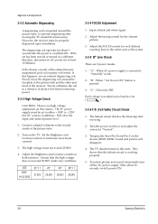
... SAME TIME (HORIZONTAL LINES) 3-7 3-3-7 Color Purity Adjustment 1. Alignment and Adjustments 6. Fully degauss the receiver. Roughly adjust convergence by rotating the Convergence Magnet. 4. Adjust the purity magnet so that the vertical green raster is precisely at the center of the screen. Tighten the Deflection Yoke clamp screw. Use an external degaussing coil. 3. Input a black and white signal. 5. Warm up the receiver. Operate it for 20 minutes, with the Brightness control set...
... SAME TIME (HORIZONTAL LINES) 3-7 3-3-7 Color Purity Adjustment 1. Alignment and Adjustments 6. Fully degauss the receiver. Roughly adjust convergence by rotating the Convergence Magnet. 4. Adjust the purity magnet so that the vertical green raster is precisely at the center of the screen. Tighten the Deflection Yoke clamp screw. Use an external degaussing coil. 3. Input a black and white signal. 5. Warm up the receiver. Operate it for 20 minutes, with the Brightness control set...
Service Manual
Page 18
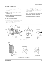
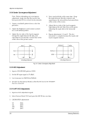
... EWC HS EWT 3-8 Samsung Electronics Adjust the two tabs of the 5-pole magnets. Input a crosshatch pattern from a color bar generator. 2. Superimpose the red/blue lines on the green. Set AGC (in the center area of the picture screen. 4. Next, turn both tabs at the center of the screen. 5. Set the RF input signal to 70 dBmV. 3. Input an AGC adjustment signal. 2. Alignment and Adjustments 3-3-8 Center Convergence Adjustment Note: Before attempting...
... EWC HS EWT 3-8 Samsung Electronics Adjust the two tabs of the 5-pole magnets. Input a crosshatch pattern from a color bar generator. 2. Superimpose the red/blue lines on the green. Set AGC (in the center area of the picture screen. 4. Next, turn both tabs at the center of the screen. 5. Set the RF input signal to 70 dBmV. 3. Input an AGC adjustment signal. 2. Alignment and Adjustments 3-3-8 Center Convergence Adjustment Note: Before attempting...
Service Manual
Page 19
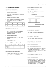
Adjust the Screen Control on the CRT PCB with a color analyzer. 4. SIZE 29" 26" 22" DC 2.4 2.4 2.4 Alignment and Adjustments 3-3-11 (D) SUB-BRIGHTNESS ADJUSTMENT 1. Input a TOSHIBA pattern. 2. NOTE : If a color analyzer is 1.4 F/L. Set high-light to 32 in the Factory Mode. 3. Set VS to 290/300 (X,Y) with an oscilloscope. 3. 3-3-11 White Balance Adjustment 3-3-11 (A) SCREEN ADJUSTMENTS 1. HEIGHT LIGHT 30" 33 ± 5 29" 37 ± 5 26" 45 ± 5 22" 45 ± 5 3-3-11 (C) SUB...
Adjust the Screen Control on the CRT PCB with a color analyzer. 4. SIZE 29" 26" 22" DC 2.4 2.4 2.4 Alignment and Adjustments 3-3-11 (D) SUB-BRIGHTNESS ADJUSTMENT 1. Input a TOSHIBA pattern. 2. NOTE : If a color analyzer is 1.4 F/L. Set high-light to 32 in the Factory Mode. 3. Set VS to 290/300 (X,Y) with an oscilloscope. 3. 3-3-11 White Balance Adjustment 3-3-11 (A) SCREEN ADJUSTMENTS 1. HEIGHT LIGHT 30" 33 ± 5 29" 37 ± 5 26" 45 ± 5 22" 45 ± 5 3-3-11 (C) SUB...
Service Manual
Page 20
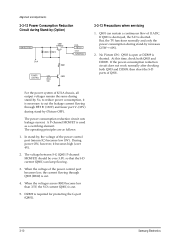
... for protecting the G-port (Q801). 3-10 Samsung Electronics So, to cut . 5. In stand-by . Alignment and Adjustments 3-3-12 Power Consumption Reduction Circuit during Stand-by increases (2.5W® 6W). 2. When the voltage of K51A chassis, all output voltages remain the same during stand-by (Picture OFF). The operating principles are as a switching element. For the power system of the power control port becomes low, the...
... for protecting the G-port (Q801). 3-10 Samsung Electronics So, to cut . 5. In stand-by . Alignment and Adjustments 3-3-12 Power Consumption Reduction Circuit during Stand-by increases (2.5W® 6W). 2. When the voltage of K51A chassis, all output voltages remain the same during stand-by (Picture OFF). The operating principles are as a switching element. For the power system of the power control port becomes low, the...
Service Manual
Page 37
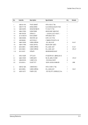
...LED 1-7 LA95-90026X ASSY-PCB,A/V 1-8 AA60-10002A SCREW-TAPPING 1-9 AA64-10749A KNOB-CONTROL 1-10 6002-000514 SCREW-TAPPING 1-11 6002-000514 SCREW-TAPPING 1-12 3001-001071 SPEAKER 2 AA03-10026R CRT-COLOR 2-1 AA60-10050R SCREW-ASSY 2-2 AA65-30004A CLAMP-D,COIL 2-3 3704-000114 SOCKET CRT 3 AA64-31183A CABINET-BACK 3-1 6002-000516 SCREW-TAPPING 3-2 AA39-10007Y POWER-CORD Specification... 1 1 1 1 1 1 1 1 2 AV+CF 1 2 KC+CF 4 SPK+CF 2 1 4 CRT+CF 8 1 V999 1 7 CB+CF 1 Samsung Electronics 5-11 Code No. Exploded Views & Parts List No.
...LED 1-7 LA95-90026X ASSY-PCB,A/V 1-8 AA60-10002A SCREW-TAPPING 1-9 AA64-10749A KNOB-CONTROL 1-10 6002-000514 SCREW-TAPPING 1-11 6002-000514 SCREW-TAPPING 1-12 3001-001071 SPEAKER 2 AA03-10026R CRT-COLOR 2-1 AA60-10050R SCREW-ASSY 2-2 AA65-30004A CLAMP-D,COIL 2-3 3704-000114 SOCKET CRT 3 AA64-31183A CABINET-BACK 3-1 6002-000516 SCREW-TAPPING 3-2 AA39-10007Y POWER-CORD Specification... 1 1 1 1 1 1 1 1 2 AV+CF 1 2 KC+CF 4 SPK+CF 2 1 4 CRT+CF 8 1 V999 1 7 CB+CF 1 Samsung Electronics 5-11 Code No. Exploded Views & Parts List No.
Service Manual
Page 42
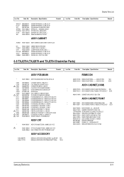
...SWITCHING;-,90~260,130/15.5/12/8V, TUNER-F/S;TECC1070PG31A(S) SOCKET-CRT;29.1PI,1.0~2.3KVD,I /B AA68-00057A MANUAL-USERS;K51A,ENG,-,B5,W/P 100(G),'Ì Samsung...LED;-,ACRYL,HB,-,-,5 INLAYF AA64-60278G INLAY-AV;-,KCT52A,PS,T0.5,BLK, INLAYB AA64-60417A INLAY-BACK;5346.46,KCT52BL/G,P KC L4082-0262-000 KNOB-CONTROL;ABSHBBLKCT-5346/46 KP L4083-0263-000 KNOB-POWER;ABSHBBLKPRINTGREEN6345/6 L/SPK AA39-20103A LEAD-CONNECTOR,ASSY;-,YSH025-0 CRT+CF AA60-10050R SCREW... Specification ...Code No. Code No. TU01 ! C-Y SPACER AA03-10030W CRT-COLOR...CORD;-,PE,HB,BLK,-,- T444 ! Electric Parts List...
...SWITCHING;-,90~260,130/15.5/12/8V, TUNER-F/S;TECC1070PG31A(S) SOCKET-CRT;29.1PI,1.0~2.3KVD,I /B AA68-00057A MANUAL-USERS;K51A,ENG,-,B5,W/P 100(G),'Ì Samsung...LED;-,ACRYL,HB,-,-,5 INLAYF AA64-60278G INLAY-AV;-,KCT52A,PS,T0.5,BLK, INLAYB AA64-60417A INLAY-BACK;5346.46,KCT52BL/G,P KC L4082-0262-000 KNOB-CONTROL;ABSHBBLKCT-5346/46 KP L4083-0263-000 KNOB-POWER;ABSHBBLKPRINTGREEN6345/6 L/SPK AA39-20103A LEAD-CONNECTOR,ASSY;-,YSH025-0 CRT+CF AA60-10050R SCREW... Specification ...Code No. Code No. TU01 ! C-Y SPACER AA03-10030W CRT-COLOR...CORD;-,PE,HB,BLK,-,- T444 ! Electric Parts List...
Service Manual
Page 43
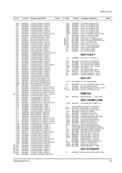
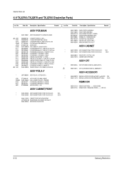
... Dissimilar Parts) Loc. Specification Remark REMOCON AA59-10112J REMOCON;DP,-,TM58,AA59-10109H,-,-,-,-, ASSY-PCB,MAIN(COM) AA97-10062B ASSY-PCB,MAIN(COM);TXJ2566/XAA,K51A,U.S 3722-001103 JACKRCA;5P ASSY-ACCESSORY AA68-00057B MANUAL-USERS;K51A,ENG 2~1µµ,B5,W/P AA68-11371A MANUAL-USERS;K51A,FRE,TM58,B5,W/P 100(G) Loc. Code No. No. Description ; Code No. Code No...
... Dissimilar Parts) Loc. Specification Remark REMOCON AA59-10112J REMOCON;DP,-,TM58,AA59-10109H,-,-,-,-, ASSY-PCB,MAIN(COM) AA97-10062B ASSY-PCB,MAIN(COM);TXJ2566/XAA,K51A,U.S 3722-001103 JACKRCA;5P ASSY-ACCESSORY AA68-00057B MANUAL-USERS;K51A,ENG 2~1µµ,B5,W/P AA68-11371A MANUAL-USERS;K51A,FRE,TM58,B5,W/P 100(G) Loc. Code No. No. Description ; Code No. Code No...
Service Manual
Page 48
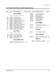
... ! AA64-40473A INDICATOR-LED;PMMA CLR CT-633 AA64-10732A KNOB-CONTROL;ABS HB BLK CT-63 AA64-10733A KNOB-POWER;ABS HB BLK CT-633 AA39-20111B LEAD-CONNECTOR,ASSY;-,YSH0253001-001039 SPEAKER;160HM,3W AA61-60003T SPRING-CS;-,-,SUS304,0.5,OD7, AA64-40472A WINDOW-REMOTE;PCVIOLET CT-633 Samsung Electronics 6-11 Code No. Code No. Description ; Description...
... ! AA64-40473A INDICATOR-LED;PMMA CLR CT-633 AA64-10732A KNOB-CONTROL;ABS HB BLK CT-63 AA64-10733A KNOB-POWER;ABS HB BLK CT-633 AA39-20111B LEAD-CONNECTOR,ASSY;-,YSH0253001-001039 SPEAKER;160HM,3W AA61-60003T SPRING-CS;-,-,SUS304,0.5,OD7, AA64-40472A WINDOW-REMOTE;PCVIOLET CT-633 Samsung Electronics 6-11 Code No. Code No. Description ; Description...
Service Manual
Page 49
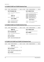
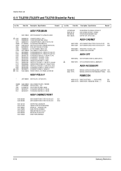
Specification Remark Loc. Code No. Specification Remark ASSY-PCB,MAIN * AA97-10063F ASSY-PCB,MAIN(OPT);TXJ2766,K51A,SAM ! T444 AA26-30005Q TRANS-FLYBACK;-,FUH-29A001(S),29/25,130 ! SUPPORT-CRT;-,HIPS,VO,BLK,-,WINDOW-REMOTE...COLOR;A68KVL74X01(D),+380MG,29,11 ASSY-ACCESSORY AA68-00057B MANUAL-USERS;K51A,ENG 2~1µµ,B5,W/P SEA AA68-11371A MANUAL-USERS... ! Electric Parts List 6-9 TXJ2766 (TXJ2879 and TXJ2766 Dissimilar Parts) Loc. ...LED;ACRYLCLR AA64-10803A AA64-10804A AA39-20111B 3001-000190 AA61-60003J AA61-40113A AA61-40042A AA64-40524A KNOB-CONTROL;ABSHBBLK KNOB-POWER...
Specification Remark Loc. Code No. Specification Remark ASSY-PCB,MAIN * AA97-10063F ASSY-PCB,MAIN(OPT);TXJ2766,K51A,SAM ! T444 AA26-30005Q TRANS-FLYBACK;-,FUH-29A001(S),29/25,130 ! SUPPORT-CRT;-,HIPS,VO,BLK,-,WINDOW-REMOTE...COLOR;A68KVL74X01(D),+380MG,29,11 ASSY-ACCESSORY AA68-00057B MANUAL-USERS;K51A,ENG 2~1µµ,B5,W/P SEA AA68-11371A MANUAL-USERS... ! Electric Parts List 6-9 TXJ2766 (TXJ2879 and TXJ2766 Dissimilar Parts) Loc. ...LED;ACRYLCLR AA64-10803A AA64-10804A AA39-20111B 3001-000190 AA61-60003J AA61-40113A AA61-40042A AA64-40524A KNOB-CONTROL;ABSHBBLK KNOB-POWER...
Service Manual
Page 50
...Code No. INDICATOR-LED;ACRYLCLR KNOB-CONTROL;ABSHBBLK KNOB-POWER;ABSHBBLK LEAD-CONNECTOR,ASSY;-,YSH025SPEAKER;5W,8OHM,89DB,150HZ SPRING-CS;-,-,SUS304,0.5,OD6, STOPPER-PCB;-,ABS,HB,NTR. AA03-10017L ASSY-CRT;A68KVL74X01(D),+380mG,29,ITC, CRT-COLOR;A68KVL74X01(D),+380MG,29,11 ASSY-ACCESSORY AA68-00057B AA68-11371A MANUAL-USERS;K51A,ENG 2~1µµ,B5,W/P SEA MANUAL-USERS...* LA97-90003N ASSY-PCB,A/V;-,KCT52A,K51A-,- Description ; Specification Remark Loc. 6-10 TXJ2767 (TXJ2879 and TXJ2767 Dissimilar Parts) Electric Parts List Loc. No. C402 C404 CN602 CB19 L401B R211 R239...
...Code No. INDICATOR-LED;ACRYLCLR KNOB-CONTROL;ABSHBBLK KNOB-POWER;ABSHBBLK LEAD-CONNECTOR,ASSY;-,YSH025SPEAKER;5W,8OHM,89DB,150HZ SPRING-CS;-,-,SUS304,0.5,OD6, STOPPER-PCB;-,ABS,HB,NTR. AA03-10017L ASSY-CRT;A68KVL74X01(D),+380mG,29,ITC, CRT-COLOR;A68KVL74X01(D),+380MG,29,11 ASSY-ACCESSORY AA68-00057B AA68-11371A MANUAL-USERS;K51A,ENG 2~1µµ,B5,W/P SEA MANUAL-USERS...* LA97-90003N ASSY-PCB,A/V;-,KCT52A,K51A-,- Description ; Specification Remark Loc. 6-10 TXJ2767 (TXJ2879 and TXJ2767 Dissimilar Parts) Electric Parts List Loc. No. C402 C404 CN602 CB19 L401B R211 R239...
Service Manual
Page 51
...;,B5,W/P SEA MANUAL-USERS;K51A,FRE,TM58,B5,W/P 100(G) SECA REMOCON AA59-10112B REMOCON;DP,TM58,-,-,-,-,-,AA59-10109B, AA59-10112G REMOCON;DP,-,TM58,AA59-10109F,-,-,-,-, SEA SECA 6-14 Samsung Electronics No. Description ; Description ; CABINET-FRONT;HIPSVOBLKBK708P SPRING-CS;-,-,SUS304,0.5,OD6, KNOB-CONTROL;ABSHBBLK WINDOW-REMOTE;PCVIOLET INDICATOR-LED;ACRYLCLR KNOB-POWER;ABSHBBLK SEA SECA Loc. Code No. No...
...;,B5,W/P SEA MANUAL-USERS;K51A,FRE,TM58,B5,W/P 100(G) SECA REMOCON AA59-10112B REMOCON;DP,TM58,-,-,-,-,-,AA59-10109B, AA59-10112G REMOCON;DP,-,TM58,AA59-10109F,-,-,-,-, SEA SECA 6-14 Samsung Electronics No. Description ; Description ; CABINET-FRONT;HIPSVOBLKBK708P SPRING-CS;-,-,SUS304,0.5,OD6, KNOB-CONTROL;ABSHBBLK WINDOW-REMOTE;PCVIOLET INDICATOR-LED;ACRYLCLR KNOB-POWER;ABSHBBLK SEA SECA Loc. Code No. No...


