

Service Manual
Page 1
Troubleshooting 6. Electric Parts List 8. Wiring Diagrams 11. COLOR TELEVISION RECEIVER Chassis : Model: K15A TXJ1366 TXJ1367 TXJ1396 TXJ1966 TXJ1996 COLOR TELEVISION RECEIVER CONTENTS 1. Alignment and Adjustments 5. PCB Layout 10. Schematic Diagrams Precautions 2. Disassembly and Reassembly 4. Block Diagram 9. Exploded Views and Parts List 7. Specifications 3.
Troubleshooting 6. Electric Parts List 8. Wiring Diagrams 11. COLOR TELEVISION RECEIVER Chassis : Model: K15A TXJ1366 TXJ1367 TXJ1396 TXJ1966 TXJ1996 COLOR TELEVISION RECEIVER CONTENTS 1. Alignment and Adjustments 5. PCB Layout 10. Schematic Diagrams Precautions 2. Disassembly and Reassembly 4. Block Diagram 9. Exploded Views and Parts List 7. Specifications 3.
Service Manual
Page 18
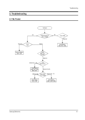
Normal ON Check IC802. Check/Replace D806, Q401, Q801, D802, D814* Normal (15~20V) Abnormal (0V) Check IC801* Normal (0.5 ~ 3V) Pin 4 Voltage Check/Replace PC802, DZ807 Check/Replace DZ802, DZ803, D806 Samsung Electronics 5-1 5. Troubleshooting 5-1 No Power Troubleshooting No Power OFF Abnormal Check Fuse. Abnormal Abnormal (0 ~ 15V) Check IC801 Pin 3 B+. Check LED when AC code is plugged. Check and Replace D807 ~D810 Check IC801* Pin 1 Oscillation. Abnormal Check/Replace IC802, R812, D856.
Normal ON Check IC802. Check/Replace D806, Q401, Q801, D802, D814* Normal (15~20V) Abnormal (0V) Check IC801* Normal (0.5 ~ 3V) Pin 4 Voltage Check/Replace PC802, DZ807 Check/Replace DZ802, DZ803, D806 Samsung Electronics 5-1 5. Troubleshooting 5-1 No Power Troubleshooting No Power OFF Abnormal Check Fuse. Abnormal Abnormal (0 ~ 15V) Check IC801 Pin 3 B+. Check LED when AC code is plugged. Check and Replace D807 ~D810 Check IC801* Pin 1 Oscillation. Abnormal Check/Replace IC802, R812, D856.
Service Manual
Page 19
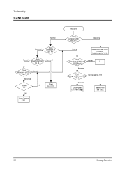
... IC201. Replace IC601 and IC602. 5-2 Samsung Electronics Normal Check Waveform of IC201 Normal Pin 1. Abnormal Normal Check CN601 and CN701 Connector Soldering and A/V PCB. Abnormal Check Voltage of IC601 Pin 1. Abnormal Volume O.K Up. No Sound Check Connector CN601 and CN701. Abnormal Check Power 12V Line Voltage. Troubleshooting 5-2 No Sound Normal Abnormal Check...
... IC201. Replace IC601 and IC602. 5-2 Samsung Electronics Normal Check Waveform of IC201 Normal Pin 1. Abnormal Normal Check CN601 and CN701 Connector Soldering and A/V PCB. Abnormal Check Voltage of IC601 Pin 1. Abnormal Volume O.K Up. No Sound Check Connector CN601 and CN701. Abnormal Check Power 12V Line Voltage. Troubleshooting 5-2 No Sound Normal Abnormal Check...

Service Manual
Page 20
5-3 Horizontal Line Appears Troubleshooting Single Horizontal Line Normal (24V) Check 24V-C Voltage. Abnormal Abnormal Check Waveform of IC201 Pins 22,24. Check FBT Pin 2 (24V) Oscillation. Samsung Electronics 5-3 Check Whether a horizontal line appears in O.K Normal the service mode.. Normal Check R409 Open. IC301. NG Check/Replace FBT. NG Check/Replace Check/Replace IC201. Open Check/Replace R409.
5-3 Horizontal Line Appears Troubleshooting Single Horizontal Line Normal (24V) Check 24V-C Voltage. Abnormal Abnormal Check Waveform of IC201 Pins 22,24. Check FBT Pin 2 (24V) Oscillation. Samsung Electronics 5-3 Check Whether a horizontal line appears in O.K Normal the service mode.. Normal Check R409 Open. IC301. NG Check/Replace FBT. NG Check/Replace Check/Replace IC201. Open Check/Replace R409.
Service Manual
Page 21
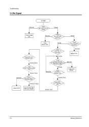
Normal Check voltage line. Normal (3~5Vp-p) Replace IC201. Check Micom IC901. Abnormal Check tuner SCL,SDA waveform. Normal Check tuner IF terminal waveform. Troubleshooting 5-4 No Signal No Signal Abnormal Check each tuner terminal voltage. Normal Check IC201 Pin 41 waveform level. Normal (2Vp-p) Check IC201 Pin 37 waveform level. ..., 21 waveform level. Check whether AGC and AFTadjustment are normal in the service mode. Check IC201 Pins 7,8 waveform. Abnormal Readjust AGC and AFT. Normal (1Vp-p) 5-4 Samsung Electronics
Normal Check voltage line. Normal (3~5Vp-p) Replace IC201. Check Micom IC901. Abnormal Check tuner SCL,SDA waveform. Normal Check tuner IF terminal waveform. Troubleshooting 5-4 No Signal No Signal Abnormal Check each tuner terminal voltage. Normal Check IC201 Pin 41 waveform level. Normal (2Vp-p) Check IC201 Pin 37 waveform level. ..., 21 waveform level. Check whether AGC and AFTadjustment are normal in the service mode. Check IC201 Pins 7,8 waveform. Abnormal Readjust AGC and AFT. Normal (1Vp-p) 5-4 Samsung Electronics


