Samsung TXJ1366 Support and Manuals
Get Help and Manuals for this Samsung item

View All Support Options Below
Free Samsung TXJ1366 manuals!
Problems with Samsung TXJ1366?
Ask a Question
Free Samsung TXJ1366 manuals!
Problems with Samsung TXJ1366?
Ask a Question
Popular Samsung TXJ1366 Manual Pages
Service Manual - Page 1

Specifications 3. Alignment and Adjustments 5. Troubleshooting 6. PCB Layout 10. Electric Parts List 8. Exploded Views and Parts List 7. Block Diagram 9. Schematic Diagrams Wiring Diagrams 11. COLOR TELEVISION RECEIVER
Chassis : Model:
K15A TXJ1366 TXJ1367 TXJ1396 TXJ1966 TXJ1996
COLOR TELEVISION RECEIVER
CONTENTS 1. Precautions 2. Disassembly and Reassembly 4.
Service Manual - Page 2

...are serviced. (X-ray protection circuits also may be measured each time servicing is done on the service data schematic. Samsung Electronics
...all of the ohmmeter to restore all exposed metal parts, including: antennas, handle brackets, metal cabinets, screwheads... the XÐray Protection Specifications Label, and the Product Safety and X-ray Warning Note on the B+, horizontal deflection...
Service Manual - Page 3

... hazards.
Do not remove, install or handle the picture tube without first putting on shatterproof goggles equipped with parts that must not be obvious from the AC power line. These safety features and the protection they give might create a safety hazard. Samsung Electronics Such alterations might be safely serviced only if the AC power...
Service Manual - Page 4

... this manual. Insulation Checking Procedure: Disconnect the power cord from the AC power source before connecting the positive lead; Never defeat any of the AC plug. Always connect a test instrumentÕs ground lead to their original position.
4. always remove the instrumentÕs ground lead last. Samsung Electronics
1-3 Warning2: An electrolytic capacitor installed with...
Service Manual - Page 7

2. Specifications
2-1 Specifications
Specifications
Television System Power Consumption
Picture Tube
Power Requirement Operating System Tuning Ranges Antenna Input Impedance Intermediate Frequency Speaker Impedance
14"/20"/21" NTSC COLOR TV SIGNAL
14" : 57 WATTS NOMINAL, 20" : 70 WATTS NOMINAL 21" : 75 WATTS ...8 ohm 3W x 2 Dual : 16 ohm , 3W x 2 (CT-33H1, CT-50H1)
Samsung Electronics
2-1
Service Manual - Page 11

Spread a soft mat on the floor. Place the TV set face down.
2. Caution: Because of the high vacuum and large surface area of the glass may cause an implosion.
3-4
Samsung Electronics Disassembly and Reassembly
3-4 CRT Removel
Fig. 3-5
1. Lift the CRT.
4. Remove the 4 nuts mounting the CRT to the front cabinet.
3. Fractures of the picture...
Service Manual - Page 12
... when either the EEPROM (IC902) or the CRT is displayed
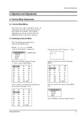
ADJUSTMENT PATTERN OPTION RESET Service Mode adjustments are no VRs in the K15A chassis, all adjustments after parts replacement must be done in STAND-BY mode:
MUTE->1->8->2->POWER "Factory Mode Menu" is replaced.
4-1-2 Entering the Service Mode
Press the following transmitter keys while in the...
Service Manual - Page 13

...not attempt to enter the set Option mode. ADJUSTMENT PATTERN OPTION RESET
Select RESET with channel w key. POWER OFF
4-1-4 Service Mode Adjustments
ADJUSTMENT PATTERN OPTION RESET
1. The Pattern Adjustment is replaced. Refer to the factory ...127
0~63
31
0~63
39
0
0
0~31
15
0~31
4
Note : The initial MICOM data values take effect when IC902 is replaced.
4-2
Samsung Electronics
Service Manual - Page 14

...service mode to set IC101
Pin 44 (AFT) to 60 dB. 3.
To enter the Service Mode, refer to produce normal picture and sound. Adjust VCO in servicing.
2. Input a PHILLIPS pattern. 2. Samsung Electronics
4-3 The TV...color TV needs only slight touch-up adjustment upon installation. Temporarily short pin X to reset. 4-2 Alignment and Adjustment
4-2-1 General Alignment Instructions
...
Service Manual - Page 15

...Adjust SCR to switch off the ABL feed-back. 3. Input a rainbow pattern.
2. Input a gray scale pattern. Set RC, BC, GC data to 2.40 ± 0.1Vp-p
2.5V_+ 0.1Vpp
4-2-10 Sub-Color Adjustment
1. Input... to 0 in the service mode until the 6th peak is the highest and the 5th and 7th peaks have equal heights.
456 3 2 1
78 9 10
2.4V_+ 0.1Vpp
4-4
Samsung Electronics Do sub-color ...
Service Manual - Page 16

...Replaced
Do the following adjustments after the basic purity and convergence adjustments. 1. Exit the horizontal line via the MUTE key.
4-2-11 (B) HIGH-LIGHT ADJUSTMENTS
1. Adjust GG,BG in low light. Receive a lion head pattern. 2. Enter the Service Mode and set...W 5 4 32 1
Samsung Electronics
4-5 Input a high-light pattern
2. Enter into
the service mode. 3. Enter the ...
Service Manual - Page 17

MEMO
4-6
Samsung Electronics
Service Manual - Page 20

...
Abnormal
Check Waveform of IC201
Pins 22,24.
Normal
Check R409 Open. 5-3 Horizontal Line Appears
Troubleshooting
Single Horizontal Line
Normal (24V)
Check 24V-C Voltage.
Check FBT Pin 2 (24V)
Oscillation.
Samsung Electronics
5-3
NG
Check/Replace FBT. Check Whether a horizontal line appears in
O.K Normal
the service mode.. NG
Check/Replace Check/Replace
IC201.
Service Manual - Page 21
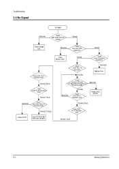
... AFTadjustment are normal in the service mode. Normal (2Vp-p)
Check IC201 Pin 37 waveform
level.
Check Micom IC901.
Normal
Abnormal Replace tuner. Normal
Abnormal
Check IC201...level.
Troubleshooting
5-4 No Signal
No Signal
Abnormal
Check each tuner terminal
voltage.
Normal
Check tuner IF terminal
waveform. Check IC201 Pins 7,8
waveform. Normal (1Vp-p)
5-4
Samsung Electronics...
Service Manual - Page 22

...
CB+CF
1
SECA
1
SEA
1
PWR/AC
6-1 Exploded Views & Parts List
6-1 TXJ1366, TXJ1367, TXJ1396
Exploded Views & Parts List
No
Code No
1
AA92-30161EA
AA64-00162A
1-1
AA64-70127F
1-2
AA64-00165B
1-3
...3-2
L7000-0132
AA42-00001A
4
AA39-10007Y
Samsung Electronics
Description
ASSY-CABINET,FRONT CABINET-FRONT BADGE...ANT-ROD
POWER-CORD
Specification
TXJ1366,9,V0,S/V,K15A 14F2,BK708P,...
Samsung TXJ1366 Reviews
We have not received any reviews for Samsung yet.