
User Manual
Page 5
... the printer are as cash drawer. 6. Characters can be selected by using your new SRP-350. ※ NOTE The socket-outlet shall be near the equipment and it 's original size. 7. The data buffer allows the unit to receive print data even during printing. 5. Bar code printing is possible by DIP switches. Please... the instruction in this manual carefully before using a bar code command. 8. The main features of external devices such as follows: 1. Low noise thermal printing. 3. ■ Introduction SRP-350 The SRP-350 Roll Printer are subjected to change without notice.
... the printer are as cash drawer. 6. Characters can be selected by using your new SRP-350. ※ NOTE The socket-outlet shall be near the equipment and it 's original size. 7. The data buffer allows the unit to receive print data even during printing. 5. Bar code printing is possible by DIP switches. Please... the instruction in this manual carefully before using a bar code command. 8. The main features of external devices such as follows: 1. Low noise thermal printing. 3. ■ Introduction SRP-350 The SRP-350 Roll Printer are subjected to change without notice.

User Manual
Page 6
......18 3. ■ Table of Contents SRP-350 1. Hexadecimal Dumping 19 4. Appendix ...21 5-1 Cleaning Printer ...21 5-2 Printing speed...21 Rev. 1.02 - 6 - Setting Up the Printer 7 1-1 Unpacking...7 1-2 Connecting the Cables 8 1-2-1 Serial Interface (RS-232C 8 1-2-2 Serial Interface (RS-485 9 1-2-3 Parallel Interface (IEEE1284 10 1-2-4 USB Interface 11 1-3 Connecting the Drawer 11 1-4 Setting the Dip Switches 12 1-4-1 Serial Interface 12 1-4-2 Parallel...
......18 3. ■ Table of Contents SRP-350 1. Hexadecimal Dumping 19 4. Appendix ...21 5-1 Cleaning Printer ...21 5-2 Printing speed...21 Rev. 1.02 - 6 - Setting Up the Printer 7 1-1 Unpacking...7 1-2 Connecting the Cables 8 1-2-1 Serial Interface (RS-232C 8 1-2-2 Serial Interface (RS-485 9 1-2-3 Parallel Interface (IEEE1284 10 1-2-4 USB Interface 11 1-3 Connecting the Drawer 11 1-4 Setting the Dip Switches 12 1-4-1 Serial Interface 12 1-4-2 Parallel...

User Manual
Page 8
... Data Ready To Send Clear To Send Data Set Ready Signal Ground Data Terminal Ready SRP-350 1-2 Connecting the Cables You can connect up the three cables to the connector panel on the back of the printer, which is shown below: ※ NOTE Before connecting any of the cables, make...8251; When the Dip Switch is "ON" on the Serial Interface Board, DTR and RTS are connected each other. They all connect to the printer. PRINTER SIDE (25P) HOST SIDE (25P) PRINTER SIDE (25P) HOST SIDE (9P) Pin No. 1 2 3 4 5 6 7 20 Signal name FG TxD RxD RTS CTS DSR SG DTR Direction - Output Input Output...
... Data Ready To Send Clear To Send Data Set Ready Signal Ground Data Terminal Ready SRP-350 1-2 Connecting the Cables You can connect up the three cables to the connector panel on the back of the printer, which is shown below: ※ NOTE Before connecting any of the cables, make...8251; When the Dip Switch is "ON" on the Serial Interface Board, DTR and RTS are connected each other. They all connect to the printer. PRINTER SIDE (25P) HOST SIDE (25P) PRINTER SIDE (25P) HOST SIDE (9P) Pin No. 1 2 3 4 5 6 7 20 Signal name FG TxD RxD RTS CTS DSR SG DTR Direction - Output Input Output...

User Manual
Page 9
PRINTER SIDE HOST SIDE Pin No. 1 2 3 4 5 7 8 9 10 11 Signal name FGND SD2 SD1 RD2 RD1 SGND DR2 DR1 CS2 CS1 Direction - Output Output Input Input - Output Input Function Frame Ground Send Data Receive Data Signal Ground Same as DTR(RS-232) Same as DSR(RS-232) Rev. 1.02 - 9 - 1-2-2 Serial Interface (RS-485) SRP-350 IFA-SF TYPE ON Interface connector Drawer kick-out Power supply connector connector ※ When the Dip Switch is "ON" on the Serial Interface Board, DTR and RTS are connected each other.
PRINTER SIDE HOST SIDE Pin No. 1 2 3 4 5 7 8 9 10 11 Signal name FGND SD2 SD1 RD2 RD1 SGND DR2 DR1 CS2 CS1 Direction - Output Output Input Input - Output Input Function Frame Ground Send Data Receive Data Signal Ground Same as DTR(RS-232) Same as DSR(RS-232) Rev. 1.02 - 9 - 1-2-2 Serial Interface (RS-485) SRP-350 IFA-SF TYPE ON Interface connector Drawer kick-out Power supply connector connector ※ When the Dip Switch is "ON" on the Serial Interface Board, DTR and RTS are connected each other.
User Manual
Page 12
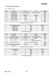
... ) 2 3 4 ( Dark ) SW - 5 ON OFF ON OFF Select Print Density SW - 6 ON OFF OFF ON Rev. 1.02 - 12 - SRP-350 1-4 Setting the Dip Switches 1-4-1 Serial Interface SW Function ON OFF 1 Auto Line Feed Always enabled Always disabled 2 Reserved - - 3 Handshaking XON/OFF DTR/DSR 4 Word length 7 bits ...8 bits 5 Parity check Yes No 6 Parity selection EVEN ODD 7 8 Baud rate selection Refer to the Following Table DIP switch Setting 1 Function Default OFF OFF OFF OFF OFF OFF ON OFF Transmission speed 9600 baud 19200 baud 38400 baud 57600 baud SW - 7 ...
... ) 2 3 4 ( Dark ) SW - 5 ON OFF ON OFF Select Print Density SW - 6 ON OFF OFF ON Rev. 1.02 - 12 - SRP-350 1-4 Setting the Dip Switches 1-4-1 Serial Interface SW Function ON OFF 1 Auto Line Feed Always enabled Always disabled 2 Reserved - - 3 Handshaking XON/OFF DTR/DSR 4 Word length 7 bits ...8 bits 5 Parity check Yes No 6 Parity selection EVEN ODD 7 8 Baud rate selection Refer to the Following Table DIP switch Setting 1 Function Default OFF OFF OFF OFF OFF OFF ON OFF Transmission speed 9600 baud 19200 baud 38400 baud 57600 baud SW - 7 ...

User Manual
Page 13
... Print Density SW - 6 ON OFF OFF ON Rev. 1.02 - 13 - OFF 3 Reserved - - OFF 7 Reserved - - OFF 4 Reserved - - SRP-350 1-4-2 Parallel & USB Interface SW Function ON OFF Default 1 Auto Line Feed Always enabled Always disabled OFF 2 Reserved - - OFF DIP switch Setting 1 Function SW Function ON OFF 1 Emulation STAR EPSON 2 Internal bell control Internal bell disable Internal...
... Print Density SW - 6 ON OFF OFF ON Rev. 1.02 - 13 - OFF 3 Reserved - - OFF 7 Reserved - - OFF 4 Reserved - - SRP-350 1-4-2 Parallel & USB Interface SW Function ON OFF Default 1 Auto Line Feed Always enabled Always disabled OFF 2 Reserved - - OFF DIP switch Setting 1 Function SW Function ON OFF 1 Emulation STAR EPSON 2 Internal bell control Internal bell disable Internal...
User Manual
Page 16
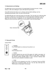
...1.02 - 16 - It has DIP switches that there is not enough paper remaining on . ○ ERROR This indicates an error. ○ PAPER This light indicates the near end of the paper roll. If you find that allow you to feed paper continuously. SRP-350 1-6 Adjustments and Settings The SRP-350 is almost out. Rotate the...is set up at front or rear position. (See the below figure) Near end sensor tab 1-7 Using the Printer Control Panel ○ POWER The POWER light is on whenever the printer is on the roll when the near-end sensor is used. ○ FEED The button can give you can...
...1.02 - 16 - It has DIP switches that there is not enough paper remaining on . ○ ERROR This indicates an error. ○ PAPER This light indicates the near end of the paper roll. If you find that allow you to feed paper continuously. SRP-350 1-6 Adjustments and Settings The SRP-350 is almost out. Rotate the...is set up at front or rear position. (See the below figure) Near end sensor tab 1-7 Using the Printer Control Panel ○ POWER The POWER light is on whenever the printer is on the roll when the near-end sensor is used. ○ FEED The button can give you can...

User Manual
Page 18
..., contact your dealer. The self-test begins. 2-3 The self-test prints the current printer status, which provides the control ROM version and the DIP switch setting. 2-4 After printing the current printer status, self-test printing will print the following ; 2-1 Make sure paper roll has ...been installed properly. 2-2 Turn on the power while holding down the FEED button. The self-test checks the following , and pause (The PAPER LED light blinks). SRP-350...
..., contact your dealer. The self-test begins. 2-3 The self-test prints the current printer status, which provides the control ROM version and the DIP switch setting. 2-4 After printing the current printer status, self-test printing will print the following ; 2-1 Make sure paper roll has ...been installed properly. 2-2 Turn on the power while holding down the FEED button. The self-test checks the following , and pause (The PAPER LED light blinks). SRP-350...

Service Manual
Page 11
... 10 11 ON RS-232 Ver.2 SRP-350/SRP-350S (RS-232C/RS-485) 1. IEEE-1284 (Parallel I /F Connector) 9b. RS-232C/RS-485 (Serial I /F Connector) 9c. Push Button 6. Power Switch Samsung Electro-Mech anics 9b 10 11 PARALLEL Ver.2 SRP-350P (PARALLEL) 9c 10 11 Ver.2 USB SRP-350U (USB) 8. Case-Upper 3. Braket Dip Switch 9a. Cover-Cutter 7. DC Power...
... 10 11 ON RS-232 Ver.2 SRP-350/SRP-350S (RS-232C/RS-485) 1. IEEE-1284 (Parallel I /F Connector) 9b. RS-232C/RS-485 (Serial I /F Connector) 9c. Push Button 6. Power Switch Samsung Electro-Mech anics 9b 10 11 PARALLEL Ver.2 SRP-350P (PARALLEL) 9c 10 11 Ver.2 USB SRP-350U (USB) 8. Case-Upper 3. Braket Dip Switch 9a. Cover-Cutter 7. DC Power...

Service Manual
Page 30
... Selection SW1 - 8 ON ON OFF OFF 3-4 Samsung Electro-Mechanics Remove the screw on the bottom of the printer and open the bracket. 3. The DIP switches are located on the bottom of the printer. Turn the printer power switch off . ON 9A 1 2 3 4 5 6 7 8 ON 9A 1 2 3 4 5 6 7 8 Note : Always change DIP switch settings only when the printer is turned off . 2. Change made with the...
... Selection SW1 - 8 ON ON OFF OFF 3-4 Samsung Electro-Mechanics Remove the screw on the bottom of the printer and open the bracket. 3. The DIP switches are located on the bottom of the printer. Turn the printer power switch off . ON 9A 1 2 3 4 5 6 7 8 ON 9A 1 2 3 4 5 6 7 8 Note : Always change DIP switch settings only when the printer is turned off . 2. Change made with the...

Service Manual
Page 31
... the Following Table Reserved - - Reserved - - SW1-1 SW1-2 SW1-3 SW1-4 SW1-5 SW1-6 SW1-7 SW1-8 FUNCTION ON OFF Auto Line Feed Reserved Always enabled - Table 3-5 DIP switch Setting 1 Function Switch No. OFF EPSON - Samsung Electro-Mechanics 3-5 SW2-1 SW2-2 SW2-3 SW2-4 SW2-5 SW2-6 SW2-7 SW2-8 FUNCTION Emulation Reserved Reserved Reserved ON STAR - OFF OFF - Reserved - - Reserved - - OFF...
... the Following Table Reserved - - Reserved - - SW1-1 SW1-2 SW1-3 SW1-4 SW1-5 SW1-6 SW1-7 SW1-8 FUNCTION ON OFF Auto Line Feed Reserved Always enabled - Table 3-5 DIP switch Setting 1 Function Switch No. OFF EPSON - Samsung Electro-Mechanics 3-5 SW2-1 SW2-2 SW2-3 SW2-4 SW2-5 SW2-6 SW2-7 SW2-8 FUNCTION Emulation Reserved Reserved Reserved ON STAR - OFF OFF - Reserved - - Reserved - - OFF...

Service Manual
Page 35
Lower 3 and the Foot-Rubber 4 from main PBA and sub assembly. 4 Disassembly and Assembly 4-1 Case-Lower Block 1 Scrw (3x8) 2 Brkt Dip Switch 4 Foot Rubber 3 Case Lower 1. Remove the connector wires from the printer. Figure 4-1 Disassembly Case-Lower #1 1. Sparate the BRKT DIP Switch 2 , the Case- Main Pcb Figure 4-2 Disassembly Case-Lower #2 Samsung Electro-Mechanics 4-1 Remove the three screws 1 . 2.
Lower 3 and the Foot-Rubber 4 from main PBA and sub assembly. 4 Disassembly and Assembly 4-1 Case-Lower Block 1 Scrw (3x8) 2 Brkt Dip Switch 4 Foot Rubber 3 Case Lower 1. Remove the connector wires from the printer. Figure 4-1 Disassembly Case-Lower #1 1. Sparate the BRKT DIP Switch 2 , the Case- Main Pcb Figure 4-2 Disassembly Case-Lower #2 Samsung Electro-Mechanics 4-1 Remove the three screws 1 . 2.

Service Manual
Page 60
Figure 7-13 DIP Switch Block Diagram Samsung Electro-Mechanics 7-9 DIP S/W1 No.1 is ON. R2 checks No.5~8 of DIP S/W#2. R4 checks No.5~8 of DIP S/W#1. R3 checks No.1~4 of DIP S/W#1. 7-8 DIP Switch Circuit 7 Special Circuit Description C4 C3 C2 C1 CPU (M30624FGFP) DIODE( MMBD6050L) R1 ~ R4 R1 (OUT) R2 (OUT) R3 (OUT) R4 (OUT) C1 (IN) C2 (IN) C3 (IN) C4 (IN) R1 checks No.1~4 of DIP S/W#2.
Figure 7-13 DIP Switch Block Diagram Samsung Electro-Mechanics 7-9 DIP S/W1 No.1 is ON. R2 checks No.5~8 of DIP S/W#2. R4 checks No.5~8 of DIP S/W#1. R3 checks No.1~4 of DIP S/W#1. 7-8 DIP Switch Circuit 7 Special Circuit Description C4 C3 C2 C1 CPU (M30624FGFP) DIODE( MMBD6050L) R1 ~ R4 R1 (OUT) R2 (OUT) R3 (OUT) R4 (OUT) C1 (IN) C2 (IN) C3 (IN) C4 (IN) R1 checks No.1~4 of DIP S/W#2.
Service Manual
Page 101
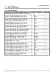
...NO DESCRIPTION / SPECIFICATION AP04-00030B PBA MAIN+LED PANEL+SENSOR Ass'y SRP-350,STD/KOR 0402-000168 DIODE-RECTIFIER;1N5822,40V,3A,DO-201 0503-000117...2SD560-R,NPN,1.5W,TO-2 1003-001102 IC-MOTOR DRIVER;TEA3718DP,DIP,16P,30 1003-001118 IC-CURRENT DRIVER;TA8428K,SIP,7P,16M...3301-000344 CORE-FERRITE BEAD;AA,-,3.5x0.6x6.5mm 3407-000177 SWITCH-DIP;5V,10mA,SLIDE,SPST 3601-000261 FUSE-CARTRIDGE;250V,3.15A,TIME...-HEADER;BOX,2P,1R,2.5mm,STR 3722-001034 JACK-MODULAR;6P/6C,-,-,ANGLE,-,-,GRA JE27-00002A COIL FILTER-;ER-350,140 UH,-,- Q'TY REMARK 1 1 D6 2 Q1,Q2 2 U9,U11 1 U3 1 U10 2 ...
...NO DESCRIPTION / SPECIFICATION AP04-00030B PBA MAIN+LED PANEL+SENSOR Ass'y SRP-350,STD/KOR 0402-000168 DIODE-RECTIFIER;1N5822,40V,3A,DO-201 0503-000117...2SD560-R,NPN,1.5W,TO-2 1003-001102 IC-MOTOR DRIVER;TEA3718DP,DIP,16P,30 1003-001118 IC-CURRENT DRIVER;TA8428K,SIP,7P,16M...3301-000344 CORE-FERRITE BEAD;AA,-,3.5x0.6x6.5mm 3407-000177 SWITCH-DIP;5V,10mA,SLIDE,SPST 3601-000261 FUSE-CARTRIDGE;250V,3.15A,TIME...-HEADER;BOX,2P,1R,2.5mm,STR 3722-001034 JACK-MODULAR;6P/6C,-,-,ANGLE,-,-,GRA JE27-00002A COIL FILTER-;ER-350,140 UH,-,- Q'TY REMARK 1 1 D6 2 Q1,Q2 2 U9,U11 1 U3 1 U10 2 ...

Service Manual
Page 105
... K204-00007A DIP SWITCH 2P 3702-001125 CONNECTOR-RIBBON 34P,FEMALE,ANGLE,AU 6021-000222 NUT-HEXAGON JE41-00467C PCB-RS232 SRP-350,FR-4,80*40 JE70-00290D IPR-BRKT RS232 SRP-270/350 Q'TY 1 1 1 6 4 1 4 1 1 1 2 1 1 REMARK D1 U1 C10 C11 C2C3C4C5 C6 C7 C8 C9 C1 L1 L2 L3 L4 CN2 SW1 CN1 Serviceable Y Y Y Y Y Y Y Y Y Y Y N Y Samsung Electro-Mechanics...
... K204-00007A DIP SWITCH 2P 3702-001125 CONNECTOR-RIBBON 34P,FEMALE,ANGLE,AU 6021-000222 NUT-HEXAGON JE41-00467C PCB-RS232 SRP-350,FR-4,80*40 JE70-00290D IPR-BRKT RS232 SRP-270/350 Q'TY 1 1 1 6 4 1 4 1 1 1 2 1 1 REMARK D1 U1 C10 C11 C2C3C4C5 C6 C7 C8 C9 C1 L1 L2 L3 L4 CN2 SW1 CN1 Serviceable Y Y Y Y Y Y Y Y Y Y Y N Y Samsung Electro-Mechanics...

Service Manual
Page 112
12 Block Diagram 12-1 SRP-350 / SRP-350S / SRP-350P / SRP-350U I/F BOARD PRINTER MEACHANISM POWER ADAPTER DC24V POWER SUPPLY VCC CIRCUIT VCC VDR(+24V) VTPH(+24V) RESET CIRCUIT FLASH AM29F800 ADDRESS DATA SRAM KM681000 ADDRESS DATA BUZZER DIP SWITCH DRAWER & COMPULSORY BUZZER CIRCUIT DIP SENSING CIRCUIT DRAWER SENSER CPU ...CONNECTOR RS-485 CONNECTOR PARALLEL CONNECTOR USB CONNECTOR SENSOR CIRCUIT AUTO CUTTER DRIVER THERMAL HEAD PAPER FEED MOTOR LED & BOTTON CIRCUIT P_END & NEAR SENSOR AUTO CUTTER A_CUT SENSOR THERMAL HEAD PAPER FEED MOTOR PANEL BOARD Samsung Electro-Mechanics 12-1
12 Block Diagram 12-1 SRP-350 / SRP-350S / SRP-350P / SRP-350U I/F BOARD PRINTER MEACHANISM POWER ADAPTER DC24V POWER SUPPLY VCC CIRCUIT VCC VDR(+24V) VTPH(+24V) RESET CIRCUIT FLASH AM29F800 ADDRESS DATA SRAM KM681000 ADDRESS DATA BUZZER DIP SWITCH DRAWER & COMPULSORY BUZZER CIRCUIT DIP SENSING CIRCUIT DRAWER SENSER CPU ...CONNECTOR RS-485 CONNECTOR PARALLEL CONNECTOR USB CONNECTOR SENSOR CIRCUIT AUTO CUTTER DRIVER THERMAL HEAD PAPER FEED MOTOR LED & BOTTON CIRCUIT P_END & NEAR SENSOR AUTO CUTTER A_CUT SENSOR THERMAL HEAD PAPER FEED MOTOR PANEL BOARD Samsung Electro-Mechanics 12-1