
User Manual
Page 2
...PROHIBITED Do not pull the cable to unplug. • This can damage the cable, which is dangerous to prevent any heavy object. • A damaged cable can cause a fire. PROHIBITED PROHIBITED Rev. 1.02 - 2 - You must use other adapters. Keep the plastic bag out of the printer. Do not plug several ...products in order to use only the supplied adapter. • It is the origin of a fire or a breakdown of children's reach. • If not, a child may put the bag on his head. SRP-350 ■ Safety Precautions In using...
...PROHIBITED Do not pull the cable to unplug. • This can damage the cable, which is dangerous to prevent any heavy object. • A damaged cable can cause a fire. PROHIBITED PROHIBITED Rev. 1.02 - 2 - You must use other adapters. Keep the plastic bag out of the printer. Do not plug several ...products in order to use only the supplied adapter. • It is the origin of a fire or a breakdown of children's reach. • If not, a child may put the bag on his head. SRP-350 ■ Safety Precautions In using...
User Manual
Page 4
SRP-350 ■ Warning - This equipment generates uses, and can take this item for environmentally safe recycling. Operation of material resources. If the printer is operated in a commercial environment. This product should turn the printer "OFF". ■ Waste Electrical and Electric Equipment (WEEE) This marking shown...the static electricity. These limits are easily damaged by the static electricity, you should turn the printer "OFF", before you connect or remove the cables on the product or its literature, indicates that is likely to cause harmful interference in accordance ...
SRP-350 ■ Warning - This equipment generates uses, and can take this item for environmentally safe recycling. Operation of material resources. If the printer is operated in a commercial environment. This product should turn the printer "OFF". ■ Waste Electrical and Electric Equipment (WEEE) This marking shown...the static electricity. These limits are easily damaged by the static electricity, you should turn the printer "OFF", before you connect or remove the cables on the product or its literature, indicates that is likely to cause harmful interference in accordance ...

User Manual
Page 6
Specification ...20 5. ■ Table of Contents SRP-350 1. Hexadecimal Dumping 19 4. Appendix ...21 5-1 Cleaning Printer ...21 5-2 Printing speed...21 Rev. 1.02 - 6 - Self Test...18 3. Setting Up the Printer 7 1-1 Unpacking...7 1-2 Connecting the Cables 8 1-2-1 Serial Interface (RS-232C 8 1-2-2 Serial Interface (RS-485 9 1-2-3 Parallel Interface (IEEE1284 10 1-2-4 USB Interface 11 1-3 Connecting the Drawer 11 1-4 Setting the Dip Switches 12...
Specification ...20 5. ■ Table of Contents SRP-350 1. Hexadecimal Dumping 19 4. Appendix ...21 5-1 Cleaning Printer ...21 5-2 Printing speed...21 Rev. 1.02 - 6 - Self Test...18 3. Setting Up the Printer 7 1-1 Unpacking...7 1-2 Connecting the Cables 8 1-2-1 Serial Interface (RS-232C 8 1-2-2 Serial Interface (RS-485 9 1-2-3 Parallel Interface (IEEE1284 10 1-2-4 USB Interface 11 1-3 Connecting the Drawer 11 1-4 Setting the Dip Switches 12...

User Manual
Page 7
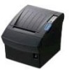
Setting Up the Printer 1-1 Unpacking Your printer box should include these items. If any items are damaged or missing, please contact your dealer for assistance. SRP-350 Cover Cable CD Roll Paper Manual AC Adapter Power Cord Rev. 1.02 - 7 - SRP-350 1.
Setting Up the Printer 1-1 Unpacking Your printer box should include these items. If any items are damaged or missing, please contact your dealer for assistance. SRP-350 Cover Cable CD Roll Paper Manual AC Adapter Power Cord Rev. 1.02 - 7 - SRP-350 1.

User Manual
Page 8
... name FG TxD RxD RTS CTS DSR SG DTR Direction - SRP-350 1-2 Connecting the Cables You can connect up the three cables to the connector panel on the back of the printer, which is shown below: ※ NOTE Before connecting any of the cables, make sure that both the printer and the host are turned off. 1-2-1 Serial Interface...
... name FG TxD RxD RTS CTS DSR SG DTR Direction - SRP-350 1-2 Connecting the Cables You can connect up the three cables to the connector panel on the back of the printer, which is shown below: ※ NOTE Before connecting any of the cables, make sure that both the printer and the host are turned off. 1-2-1 Serial Interface...
User Manual
Page 11
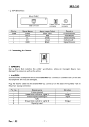
...the power supply connector. out drive signal 1 Drawer open/close signal +24V Drawer kick- Plug the drawer cable into the drawer kick-out connector on the back of the printer next to the drawer kick-out connector; Shell 1 2 3 4 USB USB connector Drawer kick-out ...Data Line(D-) Data Line(D+) Signal Ground 1-3 Connecting the Drawer ※ WARNING Use a drawer that matches the printer specification. Using an improper drawer may be damaged. Rev. 1.02 - 11 - 1-2-4 USB Interface IFA-U TYPE SRP-350 Pin No. Pin No. 1 2 3 4 5 6 Signal name Frame ground Drawer kick- Output Input ...
...the power supply connector. out drive signal 1 Drawer open/close signal +24V Drawer kick- Plug the drawer cable into the drawer kick-out connector on the back of the printer next to the drawer kick-out connector; Shell 1 2 3 4 USB USB connector Drawer kick-out ...Data Line(D-) Data Line(D+) Signal Ground 1-3 Connecting the Drawer ※ WARNING Use a drawer that matches the printer specification. Using an improper drawer may be damaged. Rev. 1.02 - 11 - 1-2-4 USB Interface IFA-U TYPE SRP-350 Pin No. Pin No. 1 2 3 4 5 6 Signal name Frame ground Drawer kick- Output Input ...

User Manual
Page 17
...Notice that the flat side of the plug faces down. ※ NOTE To remove the DC cable connector, make sure that the power supply's power cord is not plugged into the printer's interface connector. 1-8-2 Tighten the screws on the power supply to the computer. 1-9 Connecting the ... sure that of your dealer for assistance. Otherwise you may damage the power supply or the printer. SRP-350 1-8 Connecting the computer You need an appropriate interface cable. 1-8-1 Plug the cable connector securely into an electrical outlet. then grasp the connector at the arrow and pull it straight ...
...Notice that the flat side of the plug faces down. ※ NOTE To remove the DC cable connector, make sure that the power supply's power cord is not plugged into the printer's interface connector. 1-8-2 Tighten the screws on the power supply to the computer. 1-9 Connecting the ... sure that of your dealer for assistance. Otherwise you may damage the power supply or the printer. SRP-350 1-8 Connecting the computer You need an appropriate interface cable. 1-8-1 Plug the cable connector securely into an electrical outlet. then grasp the connector at the arrow and pull it straight ...

Service Manual
Page 17
... / 9600 / 19200 Bps • 7 Bit / 8 Bit • None / Even / Odd Connector • DB25P Female (I/F PBA) Note: Table2-11 RS-232C Specification 2-5-1-(b) RS-232C I/F Cable 2 Product Specifications Remark XON : ASC Code 11h XOFF : ASC Code 13h PRINTER SIDE D-SUB25P-MALE 10 mm FERRITE CORE : 1 Turn (OP-118E : 18.2 12.5 25.5) Figure 2-6 RS-232C...
... / 9600 / 19200 Bps • 7 Bit / 8 Bit • None / Even / Odd Connector • DB25P Female (I/F PBA) Note: Table2-11 RS-232C Specification 2-5-1-(b) RS-232C I/F Cable 2 Product Specifications Remark XON : ASC Code 11h XOFF : ASC Code 13h PRINTER SIDE D-SUB25P-MALE 10 mm FERRITE CORE : 1 Turn (OP-118E : 18.2 12.5 25.5) Figure 2-6 RS-232C...

Service Manual
Page 18
...-232C Cable Connection 2-5-1-(d) Signal Description Pin No. Signal Name Signal Direction Function BODY Frame GND - Signal Ground 20 DTR Output This Signal indicates whether the printer is busy. (H/W flow control) MARK(Logic1) : The printer is busy SPACE(Logic0) : The Printer is selected, the printer does... not check this signal. When XON/XOFF flow control is not busy The host transmits a data to the Operation Manual about the busy condition. 2-10 Samsung...
...-232C Cable Connection 2-5-1-(d) Signal Description Pin No. Signal Name Signal Direction Function BODY Frame GND - Signal Ground 20 DTR Output This Signal indicates whether the printer is busy. (H/W flow control) MARK(Logic1) : The printer is busy SPACE(Logic0) : The Printer is selected, the printer does... not check this signal. When XON/XOFF flow control is not busy The host transmits a data to the Operation Manual about the busy condition. 2-10 Samsung...

Service Manual
Page 19
... / 4800 / 9600 / 19200 bps • 7 Bit / 8 Bit • None / Even / Odd • DB25P Female (I/F PBA) 0.2V 0.2V Note: Table2-13 RS-485 Specification 2-5-2-(b) RS-485 I/F Cable Remark XON : ASC Code 11h XOFF : ASC Code 13h Samsung Electro-Mechanics 2-11
... / 4800 / 9600 / 19200 bps • 7 Bit / 8 Bit • None / Even / Odd • DB25P Female (I/F PBA) 0.2V 0.2V Note: Table2-13 RS-485 Specification 2-5-2-(b) RS-485 I/F Cable Remark XON : ASC Code 11h XOFF : ASC Code 13h Samsung Electro-Mechanics 2-11

Service Manual
Page 20
...Pin Description 2-12 Samsung Electro-Mechanics The host computer transmits a data to the host, after confirming this signal. The printer transmits a data to the host, after confirming this signal. Signal Name Signal Direction Function BODY Frame GND... - CS1 < CS2 (L) : The host computer is READY. When DTR/DSR is selected, this signal indicates whether the printer is BUSY or READY. (H/W flow control) DR1 > DR2 (H) : The printer is BUSY. 2 Product Specifications 2-5 Interface Specifications 2-5-2-(c) Cable Connection PRINTER SIDE ...
...Pin Description 2-12 Samsung Electro-Mechanics The host computer transmits a data to the host, after confirming this signal. The printer transmits a data to the host, after confirming this signal. Signal Name Signal Direction Function BODY Frame GND... - CS1 < CS2 (L) : The host computer is READY. When DTR/DSR is selected, this signal indicates whether the printer is BUSY or READY. (H/W flow control) DR1 > DR2 (H) : The printer is BUSY. 2 Product Specifications 2-5 Interface Specifications 2-5-2-(c) Cable Connection PRINTER SIDE ...

Service Manual
Page 23
2-5 Interface Specifications 2-5-3-(c) IEEE 1284 I/F Cable 2 Product Specifications HOST SIDE Figure 2-9 IEEE1284 Cable 2-5-4 USB Interface 2-5-4-(a) Specification Item Description Transfer Type • BULK Data Signal • Bi-direction, Half-Duplex • Differential Signal Pair (D+ / D-) Data...Threshold : 0.8 ~ 2.0[V] Speed • 12 Mbps Power • Self-Powered Cable & Connector • Cable • Connector : 5m / 2m : B Type Other • Support USB SPEC V1.1 Table2-17 USB Specification PRINTER SIDE Centronics 36P Remark Samsung Electro-Mechanics 2-15
2-5 Interface Specifications 2-5-3-(c) IEEE 1284 I/F Cable 2 Product Specifications HOST SIDE Figure 2-9 IEEE1284 Cable 2-5-4 USB Interface 2-5-4-(a) Specification Item Description Transfer Type • BULK Data Signal • Bi-direction, Half-Duplex • Differential Signal Pair (D+ / D-) Data...Threshold : 0.8 ~ 2.0[V] Speed • 12 Mbps Power • Self-Powered Cable & Connector • Cable • Connector : 5m / 2m : B Type Other • Support USB SPEC V1.1 Table2-17 USB Specification PRINTER SIDE Centronics 36P Remark Samsung Electro-Mechanics 2-15

Service Manual
Page 24
White 3 D+ Green 4 GND Black Function Frame Ground Host Power : DC5[V] / 500[mA] Differential Data Line Differential Data Line Signal Ground Table 2-18 USB Pin Description 2-5-4-(c) USB I/F Cable Figure 2-10 USB Cable 2-16 Samsung Electro-Mechanics Signal Name Assignment(Color) Shell Shield Drain Wire 1 VBUS Red 2 D- 2 Product Specifications 2-5 Interface Specifications 2-5-4-(b) Signal Description Pin No.
White 3 D+ Green 4 GND Black Function Frame Ground Host Power : DC5[V] / 500[mA] Differential Data Line Differential Data Line Signal Ground Table 2-18 USB Pin Description 2-5-4-(c) USB I/F Cable Figure 2-10 USB Cable 2-16 Samsung Electro-Mechanics Signal Name Assignment(Color) Shell Shield Drain Wire 1 VBUS Red 2 D- 2 Product Specifications 2-5 Interface Specifications 2-5-4-(b) Signal Description Pin No.
Service Manual
Page 25
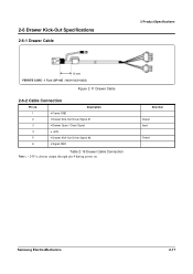
Description 1 • Frame GND 2 • Drawer Kick-Out Driver Signal #1 3 • Drawer Open / Close Signal 4 • +24V 5 • Drawer Kick-Out Driver Signal #2 6 • Signal GND Table 2-19 Drawer Cable Connection Direction Output Input Output - 2-6 Drawer Kick-Out Specifications 2-6-1 Drawer Cable 2 Product Specifications 10 mm FERRITE CORE : 1 Turn (OP-18E : 18.2 12.5 25.5) Figure 2-11 Drawer Cable 2-6-2 Cable Connection Pin no. Samsung Electro-Mechanics 2-17
Description 1 • Frame GND 2 • Drawer Kick-Out Driver Signal #1 3 • Drawer Open / Close Signal 4 • +24V 5 • Drawer Kick-Out Driver Signal #2 6 • Signal GND Table 2-19 Drawer Cable Connection Direction Output Input Output - 2-6 Drawer Kick-Out Specifications 2-6-1 Drawer Cable 2 Product Specifications 10 mm FERRITE CORE : 1 Turn (OP-18E : 18.2 12.5 25.5) Figure 2-11 Drawer Cable 2-6-2 Cable Connection Pin no. Samsung Electro-Mechanics 2-17

Service Manual
Page 27
... Connector Serial Interface Cable Figure3-2 I /F connector on the printer. 3. Load the paper roll on the printer, host ECR and computer. Turn the printer off the printer, host ECR and Computer. 2. Plug the drawer kick-out cable connector into the I /F Cable Installation 1. Turn ... Make sure the printer is one. 2. 3 Installation and Operation 3-1 Installation 3-1-1 AC Adapter Installation 3-1-3 Drawer Cable Installation Power Connector AC Adapter Drawer Kick-Out Connector Drawer Kick-Out Cable Figure3-1 AC Adapter Installation Figure3-3 Drawer Cable Installation 1. Plug the...
... Connector Serial Interface Cable Figure3-2 I /F connector on the printer. 3. Load the paper roll on the printer, host ECR and computer. Turn the printer off the printer, host ECR and Computer. 2. Plug the drawer kick-out cable connector into the I /F Cable Installation 1. Turn ... Make sure the printer is one. 2. 3 Installation and Operation 3-1 Installation 3-1-1 AC Adapter Installation 3-1-3 Drawer Cable Installation Power Connector AC Adapter Drawer Kick-Out Connector Drawer Kick-Out Cable Figure3-1 AC Adapter Installation Figure3-3 Drawer Cable Installation 1. Plug the...

Service Manual
Page 36
Sparate the BRKT Serial 232 3 (Parallel, 485). 3. Separate the Cover-Cable 2 from the BRKT PCB 2 . Separate the Main PBA 6 from the CaseLower 1 . 2 Cover Cabel Figure 4-4 Disassembly Case-Lower #4 4-2 Samsung Electro-Mechanics Remove the two screws 4 . 4. Separate the BRKT Serial 3 from the BRKT PBA 2 . 2. Remove the four screws 7 . 7. Remove the three screws 1 , 8 from the...
Sparate the BRKT Serial 232 3 (Parallel, 485). 3. Separate the Cover-Cable 2 from the BRKT PCB 2 . Separate the Main PBA 6 from the CaseLower 1 . 2 Cover Cabel Figure 4-4 Disassembly Case-Lower #4 4-2 Samsung Electro-Mechanics Remove the two screws 4 . 4. Separate the BRKT Serial 3 from the BRKT PBA 2 . 2. Remove the four screws 7 . 7. Remove the three screws 1 , 8 from the...

Service Manual
Page 37
...Cable 1 Push Button Figure 4-5 Disassembly Case-Upper #1 3 1 Screw (3x4) 6 Case Upper 1. Remove the three screws 4 . 4. Remove the four screws 2 . 3. Remove the two screws 1 . 2. Push the button 1 to open 1. Separate the Cover-Open 3 . 4. Separate the Manual-Cutter 5 from the Case-Upper 6 . 4 Screw (3x4) 5 Manual Cutter 2 Push Button Figure 4-6 Disassembly Case-Upper #2 Samsung... Electro-Mechanics 4-3 Lift the Case-Upper in the direction of an arrow 3 during pushing the Push-Button 2 . 3. Separate...
...Cable 1 Push Button Figure 4-5 Disassembly Case-Upper #1 3 1 Screw (3x4) 6 Case Upper 1. Remove the three screws 4 . 4. Remove the four screws 2 . 3. Remove the two screws 1 . 2. Push the button 1 to open 1. Separate the Cover-Open 3 . 4. Separate the Manual-Cutter 5 from the Case-Upper 6 . 4 Screw (3x4) 5 Manual Cutter 2 Push Button Figure 4-6 Disassembly Case-Upper #2 Samsung... Electro-Mechanics 4-3 Lift the Case-Upper in the direction of an arrow 3 during pushing the Push-Button 2 . 3. Separate...

Service Manual
Page 82
Y N 1. Check the generated Frequency End Samsung Electro-Mechanics 9-1 Check the Input/Output Power Cable 2. Y Power VCC (+5V) Ok? Check the On/Off Signal on CPU N 1. Check the Fuse(FU1) 2. Check the Harness of Power S/W 3. Replace the Adapter(SMPS). Power ...? Check the IC34063(U5) 2. Check the TR(Q3, Q4) 2. Check the related Circuit & Pattern N 1. 9 Troubleshooting This chapter describes the methods for troubleshooting in this Receipt Printer. 9-1 Power Problem Power Problem Power Out N Ok?
Y N 1. Check the generated Frequency End Samsung Electro-Mechanics 9-1 Check the Input/Output Power Cable 2. Y Power VCC (+5V) Ok? Check the On/Off Signal on CPU N 1. Check the Fuse(FU1) 2. Check the Harness of Power S/W 3. Replace the Adapter(SMPS). Power ...? Check the IC34063(U5) 2. Check the TR(Q3, Q4) 2. Check the related Circuit & Pattern N 1. 9 Troubleshooting This chapter describes the methods for troubleshooting in this Receipt Printer. 9-1 Power Problem Power Problem Power Out N Ok?

Service Manual
Page 88
... Signal is open or short 3. Check the connection of the RS-232C Connector and Other side 2. Check the I/F Cable whether it is open or short 3. Check the I /F PBA 5. Confirm the H/W handshaking Protocol End Samsung Electro-Mechanics 9-7 9-7 RS-232C Serial Communication Problem 9 Troubleshooting RS-232C Problem Communication Y Failure? Check the MAX232 Driving Chip...
... Signal is open or short 3. Check the connection of the RS-232C Connector and Other side 2. Check the I/F Cable whether it is open or short 3. Check the I /F PBA 5. Confirm the H/W handshaking Protocol End Samsung Electro-Mechanics 9-7 9-7 RS-232C Serial Communication Problem 9 Troubleshooting RS-232C Problem Communication Y Failure? Check the MAX232 Driving Chip...

Service Manual
Page 89
...open or short 3. Check the I /F PBA 5. Check the Txd, Rxd Pin on I /F Cable whether it is open or short 3. Check the connection of each Line End 9-8 Samsung Electro-Mechanics Confirm the H/W handshaking Protocol 4. N 1. Check the Voltage Level of the H/W handshaking ...Line and Other side(DR1,2/CS1,2) 2. Check whether Signal is affected by the Cable Noise H/W Handshake Y N 1. Check the ...
...open or short 3. Check the I /F PBA 5. Check the Txd, Rxd Pin on I /F Cable whether it is open or short 3. Check the connection of each Line End 9-8 Samsung Electro-Mechanics Confirm the H/W handshaking Protocol 4. N 1. Check the Voltage Level of the H/W handshaking ...Line and Other side(DR1,2/CS1,2) 2. Check whether Signal is affected by the Cable Noise H/W Handshake Y N 1. Check the ...