
Service Manual
Page 1
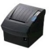
Precaution Statements 2. Commands 9. Block Diagram 13. Wiring Diagram 14. Product Specification 3. Troubleshooting 10. Maintenance and Adjustment 6. Installation and Operation 4. Special Circuit Descriptions 8. Schematic Diagrams Reference Information 7. PCB Layout and Parts List 12. Exploded Views and Parts List 11. Disassembly and Assembly 5. THERMAL RECEIPT PRINTER SRP-350 Ver.2 Series SRP-350/350S/350P/350U SRP-350G/350SG/350PG/350UG SERVICE Manual THERMAL RECEIT PRINTER CONTENTS 1.
Precaution Statements 2. Commands 9. Block Diagram 13. Wiring Diagram 14. Product Specification 3. Troubleshooting 10. Maintenance and Adjustment 6. Installation and Operation 4. Special Circuit Descriptions 8. Schematic Diagrams Reference Information 7. PCB Layout and Parts List 12. Exploded Views and Parts List 11. Disassembly and Assembly 5. THERMAL RECEIPT PRINTER SRP-350 Ver.2 Series SRP-350/350S/350P/350U SRP-350G/350SG/350PG/350UG SERVICE Manual THERMAL RECEIT PRINTER CONTENTS 1.

Service Manual
Page 82
... N 1. Check the Fuse(FU1) 2. Check the TR(Q3, Q4) 2. Check the related Circuit & Pattern 3. Y N 1. Check the generated Frequency End Samsung Electro-Mechanics 9-1 9 Troubleshooting This chapter describes the methods for troubleshooting in this Receipt Printer. 9-1 Power Problem Power Problem Power Out N Ok? Check the Input/Output Power Cable 2. Check the Harness of Power S/W 3. On SMPS...
... N 1. Check the Fuse(FU1) 2. Check the TR(Q3, Q4) 2. Check the related Circuit & Pattern 3. Y N 1. Check the generated Frequency End Samsung Electro-Mechanics 9-1 9 Troubleshooting This chapter describes the methods for troubleshooting in this Receipt Printer. 9-1 Power Problem Power Problem Power Out N Ok? Check the Input/Output Power Cable 2. Check the Harness of Power S/W 3. On SMPS...

Service Manual
Page 83
... SRAM 3. Check the Main Clock(16.00MHz) 2. Y Clock Signal Ok? Y N 1. Check the Reset Pin on PCB N 1. Y N 1. 9 Troubleshooting 9-2 System Problem System Problem Reset Signal Ok? Check the Addr/Data Line Pattern 2. Check the Main PBA End 9-2 Samsung Electro-Mechanics Y SRAM Ok? Check the related Circuit & Pattern on Flash Memory 3. Check the Addr/Data...
... SRAM 3. Check the Main Clock(16.00MHz) 2. Y Clock Signal Ok? Y N 1. Check the Reset Pin on PCB N 1. Y N 1. 9 Troubleshooting 9-2 System Problem System Problem Reset Signal Ok? Check the Addr/Data Line Pattern 2. Check the Main PBA End 9-2 Samsung Electro-Mechanics Y SRAM Ok? Check the related Circuit & Pattern on Flash Memory 3. Check the Addr/Data...

Service Manual
Page 84
... Main PBA 2. Y End N 1. Check and Replace the P_End Sensor N 1. Check the Cover Sensor Signal on Main PBA 2. Check the Harness 4. 9-3 Panel PBA and Sensor Problem 9 Troubleshooting Panel PBA Problem LED Ok? Replace the Panel PBA N 1. Check the LED Signal from CPU on Main PBA 2. Check the related Circuit, Pattern & Component Paper...
... Main PBA 2. Y End N 1. Check and Replace the P_End Sensor N 1. Check the Cover Sensor Signal on Main PBA 2. Check the Harness 4. 9-3 Panel PBA and Sensor Problem 9 Troubleshooting Panel PBA Problem LED Ok? Replace the Panel PBA N 1. Check the LED Signal from CPU on Main PBA 2. Check the related Circuit, Pattern & Component Paper...
Service Manual
Page 85
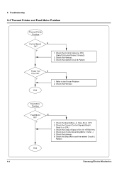
...Signals(StepI0, StepI1) on CPU (Data/CLK/Latch/Strobe1,Strobe2) 2. Check the Output Signal of U9, U11(TEA3718) 4. Check the Harness 3. Y N 1. Y 1. 9 Troubleshooting 9-4 Thermal Printer and Feed Motor Problem Thermal Printer Problem Control Signal N Ok? Refer to the Power Problem 2. Check the Signal(Step_A, Step_B) on CPU 2. Check the Harness 6. Check the related Circuit... HArness Feed Motor Problem Feed Motor Ok? Check Auto Cutter Assembly(Motor, Cutter...) 5. Check the Step Motor and the related Circuit & Pattern End 9-4 Samsung Electro-Mechanics Y End N 1.
...Signals(StepI0, StepI1) on CPU (Data/CLK/Latch/Strobe1,Strobe2) 2. Check the Output Signal of U9, U11(TEA3718) 4. Check the Harness 3. Y N 1. Y 1. 9 Troubleshooting 9-4 Thermal Printer and Feed Motor Problem Thermal Printer Problem Control Signal N Ok? Refer to the Power Problem 2. Check the Signal(Step_A, Step_B) on CPU 2. Check the Harness 6. Check the related Circuit... HArness Feed Motor Problem Feed Motor Ok? Check Auto Cutter Assembly(Motor, Cutter...) 5. Check the Step Motor and the related Circuit & Pattern End 9-4 Samsung Electro-Mechanics Y End N 1.

Service Manual
Page 86
Check the Solenoid in the Drawer Samsung Electro-Mechanics 9-5 Check the Micro switch in the Drawer Compulsory Failure? Y Auto Cutter S/W Ok? Check the Signal on CPU(P1.6/P1.7) 3. Check the Drawer ...& Connector 2. Check the Signal on CPU 2. Check the Output Signal of U3(TA8428K) 3. Check the Auto Cutter Assembly(Motor, Cutter...) N 1. 9-5 Auto Cutter and Drawer Problem 9 Troubleshooting Auto Cutter Problem Auto Cutter Ok? Check the Drawer Connector & Harness 2. Check the related circuit & Component D560(Q1, Q2) 4. Y End Drawer Problem N 1. Check the Micro...
Check the Solenoid in the Drawer Samsung Electro-Mechanics 9-5 Check the Micro switch in the Drawer Compulsory Failure? Y Auto Cutter S/W Ok? Check the Signal on CPU(P1.6/P1.7) 3. Check the Drawer ...& Connector 2. Check the Signal on CPU 2. Check the Output Signal of U3(TA8428K) 3. Check the Auto Cutter Assembly(Motor, Cutter...) N 1. 9-5 Auto Cutter and Drawer Problem 9 Troubleshooting Auto Cutter Problem Auto Cutter Ok? Check the Drawer Connector & Harness 2. Check the related circuit & Component D560(Q1, Q2) 4. Y End Drawer Problem N 1. Check the Micro...

Service Manual
Page 87
Check the Input Signal(DIP C1~C4) 4. Check the Diode on CPU 2. Check the related Circuit & Pattern End 9-6 Samsung Electro-Mechanics Check the Output Signal(I/F Sel) on I/F PBA 3. Check the Diode(D7~D22) 3. Check the Input Signal(DIP C1~C4) 4. Y N 1. Check the Output Signal(DIP R1~4) 2. Check the related Circuit & Pattern End I/F PBA Select Problem I /F PBA Select Problem DIP S/W Problem DIP S/W Input Ok? 9 Troubleshooting 9-6 DIP S/W and I /F PBA Select Ok? Y N 1.
Check the Input Signal(DIP C1~C4) 4. Check the Diode on CPU 2. Check the related Circuit & Pattern End 9-6 Samsung Electro-Mechanics Check the Output Signal(I/F Sel) on I/F PBA 3. Check the Diode(D7~D22) 3. Check the Input Signal(DIP C1~C4) 4. Y N 1. Check the Output Signal(DIP R1~4) 2. Check the related Circuit & Pattern End I/F PBA Select Problem I /F PBA Select Problem DIP S/W Problem DIP S/W Input Ok? 9 Troubleshooting 9-6 DIP S/W and I /F PBA Select Ok? Y N 1.

Service Manual
Page 88
... is affected by the Cable Noise H/W Handshake Y N 1. Check the I /F PBA 5. Check the MAX232 Driving Chip and reated Circuit on CPU 4. Confirm the H/W handshaking Protocol End Samsung Electro-Mechanics 9-7 N 1. Check the connection of the RS-232C Connector and Other side 2. 9-7 RS-232C Serial Communication Problem 9 Troubleshooting RS-232C Problem Communication Y Failure?
... is affected by the Cable Noise H/W Handshake Y N 1. Check the I /F PBA 5. Check the MAX232 Driving Chip and reated Circuit on CPU 4. Confirm the H/W handshaking Protocol End Samsung Electro-Mechanics 9-7 N 1. Check the connection of the RS-232C Connector and Other side 2. 9-7 RS-232C Serial Communication Problem 9 Troubleshooting RS-232C Problem Communication Y Failure?

Service Manual
Page 89
... 3. Confirm the H/W handshaking Protocol 4. Check the Voltage Level of the RS-485 Connector and Other side 2. 9 Troubleshooting 9-8 RS-485 Serial Communication Problem RS-485 Problem Communication Y Failure? Check the connection of each Line End 9-8 Samsung Electro-Mechanics Check the connection of the H/W handshaking Line and Other side(DR1,2/CS1,2) 2. N 1. Check the Txd...
... 3. Confirm the H/W handshaking Protocol 4. Check the Voltage Level of the RS-485 Connector and Other side 2. 9 Troubleshooting 9-8 RS-485 Serial Communication Problem RS-485 Problem Communication Y Failure? Check the connection of each Line End 9-8 Samsung Electro-Mechanics Check the connection of the H/W handshaking Line and Other side(DR1,2/CS1,2) 2. N 1. Check the Txd...

Service Manual
Page 90
... Reverse Mode Y Failure? Check the Signal of ICs(U3, U6, U5) 4. Check the Control Line(CS3) 2. N 1. Check the related Circuit and Pattern on I /F PBA End Samsung Electro-Mechanics 9-9 Check the Signal of ICs(U1, U3, U6) 4. Check the 1284 Cable whether it is open or short 5. Check the 1284 Control Line...
... Reverse Mode Y Failure? Check the Signal of ICs(U3, U6, U5) 4. Check the Control Line(CS3) 2. N 1. Check the related Circuit and Pattern on I /F PBA End Samsung Electro-Mechanics 9-9 Check the Signal of ICs(U1, U3, U6) 4. Check the 1284 Cable whether it is open or short 5. Check the 1284 Control Line...

Service Manual
Page 91
... Line & Signal(CS3, RD, WR, INT) 2. Check the related Circuit and Pattern on I/F PBA 9-10 Samsung Electro-Mechanics Check the related Circuit and Pattern on I /F Y Failure? Check the Connector(34P) 4. N End Y 1. Check the Clock(48MHz) 5. 9 Troubleshooting 9-10 USB Communication Problem USB Problem Main PBA I /F PBA & Main PBA Host Comm Failure? Check the...
... Line & Signal(CS3, RD, WR, INT) 2. Check the related Circuit and Pattern on I/F PBA 9-10 Samsung Electro-Mechanics Check the related Circuit and Pattern on I /F Y Failure? Check the Connector(34P) 4. N End Y 1. Check the Clock(48MHz) 5. 9 Troubleshooting 9-10 USB Communication Problem USB Problem Main PBA I /F PBA & Main PBA Host Comm Failure? Check the...