User Manual
Page 6
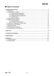
SRP-350 ■ Table of Contents 1. Appendix ...21 5-1 Cleaning Printer ...21 5-2 Printing speed...21 Rev. 1.07 - 6 - Self Test...18 3. Hexadecimal Dumping 19 4. Setting Up the Printer 7 1-1 ... 1-4-2 Parallel & USB Interface 13 1-5 Installing or Replacing the Paper Roll 14 1-6 Adjustments and Settings 16 1-7 Using the Printer ...16 1-8 Connecting the computer 17 1-9 Connecting the Power Supply 17 2. Specification ...20 5.
SRP-350 ■ Table of Contents 1. Appendix ...21 5-1 Cleaning Printer ...21 5-2 Printing speed...21 Rev. 1.07 - 6 - Self Test...18 3. Hexadecimal Dumping 19 4. Setting Up the Printer 7 1-1 ... 1-4-2 Parallel & USB Interface 13 1-5 Installing or Replacing the Paper Roll 14 1-6 Adjustments and Settings 16 1-7 Using the Printer ...16 1-8 Connecting the computer 17 1-9 Connecting the Power Supply 17 2. Specification ...20 5.
User Manual
Page 7
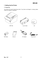
Setting Up the Printer 1-1 Unpacking Your printer box should include these items. If any items are damaged or missing, please contact your dealer for assistance. SRP-350 Cover Cable CD Roll Paper Manual AC Adapter Power Cord Rev. 1.07 - 7 - SRP-350 1.
Setting Up the Printer 1-1 Unpacking Your printer box should include these items. If any items are damaged or missing, please contact your dealer for assistance. SRP-350 Cover Cable CD Roll Paper Manual AC Adapter Power Cord Rev. 1.07 - 7 - SRP-350 1.
User Manual
Page 8
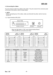
... Input Output - SRP-350 1-2 Connecting the Cables You can connect up the three cables to the connector panel on the back of the cables, make sure that both the printer and the host are turned off. 1-2-1 Serial Interface (RS-232C) IFA-S TYPE ON Interface connector Drawer kick-out Power supply connector connector...
... Input Output - SRP-350 1-2 Connecting the Cables You can connect up the three cables to the connector panel on the back of the cables, make sure that both the printer and the host are turned off. 1-2-1 Serial Interface (RS-232C) IFA-S TYPE ON Interface connector Drawer kick-out Power supply connector connector...
User Manual
Page 9
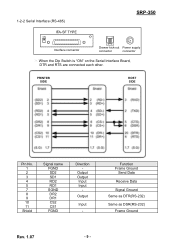
1-2-2 Serial Interface (RS-485) SRP-350 IFA-SF TYPE ON Interface connector Drawer kick-out Power supply connector connector ※ When the Dip Switch is "ON" on the Serial Interface Board, DTR and RTS are connected each other. Output Output Input Input - Output Input - Function Frame Ground Send Data Receive Data Signal Ground Same as DTR(RS-232) Same as DSR(RS-232) Frame Ground Rev. 1.07 - 9 - PRINTER SIDE HOST SIDE Pin No. 1 2 3 4 5 7 8 9 10 11 Shield Signal name FGND SD2 SD1 RD2 RD1 SGND DR2 DR1 CS2 CS1 FGND Direction -
1-2-2 Serial Interface (RS-485) SRP-350 IFA-SF TYPE ON Interface connector Drawer kick-out Power supply connector connector ※ When the Dip Switch is "ON" on the Serial Interface Board, DTR and RTS are connected each other. Output Output Input Input - Output Input - Function Frame Ground Send Data Receive Data Signal Ground Same as DTR(RS-232) Same as DSR(RS-232) Frame Ground Rev. 1.07 - 9 - PRINTER SIDE HOST SIDE Pin No. 1 2 3 4 5 7 8 9 10 11 Shield Signal name FGND SD2 SD1 RD2 RD1 SGND DR2 DR1 CS2 CS1 FGND Direction -

User Manual
Page 10
1-2-3 Parallel Interface (IEEE1284) IFA-P TYPE SRP-350 Interface connector Drawer kick-out Power supply connector connector Pin No. 1 2 3 4 5 6 7 8 9 10 11 12 13 14 15 16 17 18 19~30 31 32 33 34 35 36 Source Host Host / ...
1-2-3 Parallel Interface (IEEE1284) IFA-P TYPE SRP-350 Interface connector Drawer kick-out Power supply connector connector Pin No. 1 2 3 4 5 6 7 8 9 10 11 12 13 14 15 16 17 18 19~30 31 32 33 34 35 36 Source Host Host / ...
User Manual
Page 11
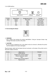
1-2-4 USB Interface IFA-U TYPE SRP-350 Pin No. otherwise the printer and the telephone line may damage the drawer as well as the printer. ※ CAUTION - Rev. 1.07 - 11 - Do not connect a telephone line to the power supply connector. out drive signal 1 Drawer open/close signal +24V Drawer kick- ... connector connector Signal Name Shield VBUS DD+ GND Assignment (Color) Drain Wire Red White Green Black Function Frame Ground Host Power Data Line(D-) Data Line(D+) Signal Ground 1-3 Connecting the Drawer ※ WARNING - Using an improper drawer may be damaged. Pin No. 1 2 3 4...
1-2-4 USB Interface IFA-U TYPE SRP-350 Pin No. otherwise the printer and the telephone line may damage the drawer as well as the printer. ※ CAUTION - Rev. 1.07 - 11 - Do not connect a telephone line to the power supply connector. out drive signal 1 Drawer open/close signal +24V Drawer kick- ... connector connector Signal Name Shield VBUS DD+ GND Assignment (Color) Drain Wire Red White Green Black Function Frame Ground Host Power Data Line(D-) Data Line(D+) Signal Ground 1-3 Connecting the Drawer ※ WARNING - Using an improper drawer may be damaged. Pin No. 1 2 3 4...
User Manual
Page 16
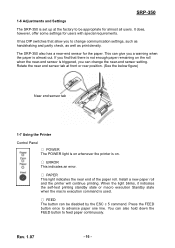
... and Settings The SRP-350 is set up at front or rear position. (See the below figure) Near end sensor tab 1-7 Using the Printer Control Panel ○ POWER The POWER light is on whenever the printer is on the roll when the near-end sensor is triggered, you can change communication settings, ...such as handshaking and parity check, as well as print density. The SRP-350 also has a near end of the paper...
... and Settings The SRP-350 is set up at front or rear position. (See the below figure) Near end sensor tab 1-7 Using the Printer Control Panel ○ POWER The POWER light is on whenever the printer is on the roll when the near-end sensor is triggered, you can change communication settings, ...such as handshaking and parity check, as well as print density. The SRP-350 also has a near end of the paper...
User Manual
Page 17
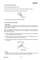
...'s rated voltage and your outlet's voltage do not match, contact your electrical outlet. 1-9-3 Plug in the power cord. To remove the DC cable connector, make sure that the power supply is unplugged; SRP-350 1-8 Connecting the computer You need an appropriate interface cable. 1-8-1 Plug the cable connector securely into an electrical outlet. When...
...'s rated voltage and your outlet's voltage do not match, contact your electrical outlet. 1-9-3 Plug in the power cord. To remove the DC cable connector, make sure that the power supply is unplugged; SRP-350 1-8 Connecting the computer You need an appropriate interface cable. 1-8-1 Plug the cable connector securely into an electrical outlet. When...
User Manual
Page 18
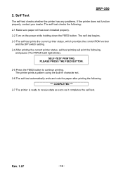
... the self-test. The self-test checks the following . *** COMPLETED *** 2-7 The printer is ready to continue printing. Rev. 1.07 - 18 - SRP-350 2. SELF-TEST PRINTING. The printer prints a pattern using the built-in character set. 2-6 The self-test automatically ends and cuts the paper after ...printing the following ; 2-1 Make sure paper roll has been installed properly. 2-2 Turn on the power while holding down the FEED button. Self Test The self-test checks whether the printer has any problems. If the printer does not function properly...
... the self-test. The self-test checks the following . *** COMPLETED *** 2-7 The printer is ready to continue printing. Rev. 1.07 - 18 - SRP-350 2. SELF-TEST PRINTING. The printer prints a pattern using the built-in character set. 2-6 The self-test automatically ends and cuts the paper after ...printing the following ; 2-1 Make sure paper roll has been installed properly. 2-2 Turn on the power while holding down the FEED button. Self Test The self-test checks whether the printer has any problems. If the printer does not function properly...