Operation Manual
Page 1
SRP-270 SERIES 1 STATION PRINTER Operator's Manual All specifications are subjected to change without notice
SRP-270 SERIES 1 STATION PRINTER Operator's Manual All specifications are subjected to change without notice
Operation Manual
Page 2
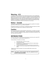
.... 2. 2 color dot-matrix printer. 3. The data buffer allows the unit to correct the interference at his own expense. NOTE : The power-outlet should be required to receive print data even during printing. 5. Operation of this manual carefully before you should turn the printer "OFF", before using...dans les reglements d'interference radio. If the printer is operated in which case the user will help protect the printer against harmful interference when the equipment is damaged by static electricity. INTRODUCTION The SRP-270 Roll Printers are easily damaged by the static electricity, ...
.... 2. 2 color dot-matrix printer. 3. The data buffer allows the unit to correct the interference at his own expense. NOTE : The power-outlet should be required to receive print data even during printing. 5. Operation of this manual carefully before you should turn the printer "OFF", before using...dans les reglements d'interference radio. If the printer is operated in which case the user will help protect the printer against harmful interference when the equipment is damaged by static electricity. INTRODUCTION The SRP-270 Roll Printers are easily damaged by the static electricity, ...
Operation Manual
Page 3
... PAPER 34 3 SETTING THE DIP SWITCHES 13 CHAPTER 5. CONNECTING INTERFACE CABLE AND DRAWER 7 CHAPTER 3. THE SELF TEST 17 CHAPTER 7. CHECKING THE CONTENTS OF THE PRINTER BOX 4 1-2. FUNCTIONS 5 CHAPTER 2. CONNECTING THE AC ADAPTER TO THE PRINTER 6 2-2. INSTALLING THE ROLL PAPER 8 3-1. LOCATING THE PRINTER 4 1-3. RIBBON CASSETTE INSTALLATION 8 3-2. UNPACKING 4 1-1. CONNECTING THE CABLES 6 2-1. HEXADECIMAL DUMPING 16 CHAPTER 6.
... PAPER 34 3 SETTING THE DIP SWITCHES 13 CHAPTER 5. CONNECTING INTERFACE CABLE AND DRAWER 7 CHAPTER 3. THE SELF TEST 17 CHAPTER 7. CHECKING THE CONTENTS OF THE PRINTER BOX 4 1-2. FUNCTIONS 5 CHAPTER 2. CONNECTING THE AC ADAPTER TO THE PRINTER 6 2-2. INSTALLING THE ROLL PAPER 8 3-1. LOCATING THE PRINTER 4 1-3. RIBBON CASSETTE INSTALLATION 8 3-2. UNPACKING 4 1-1. CONNECTING THE CABLES 6 2-1. HEXADECIMAL DUMPING 16 CHAPTER 6.

Operation Manual
Page 4
.... 4 l Make sure that there is enough space around the printer so that all the necessary accessories are included in a dusty or dirty area. Checking the Contents of the printer. l Avoid using or storing the printer in direct sunlight or subject to excessive heat. Avoid places subject... to excessive moisture. l Choose a stable and flat place for proper use or store the printer in the package. 1-2. Installing the printer l Avoid locations in places...
.... 4 l Make sure that there is enough space around the printer so that all the necessary accessories are included in a dusty or dirty area. Checking the Contents of the printer. l Avoid using or storing the printer in direct sunlight or subject to excessive heat. Avoid places subject... to excessive moisture. l Choose a stable and flat place for proper use or store the printer in the package. 1-2. Installing the printer l Avoid locations in places...
Operation Manual
Page 5
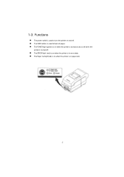
Functions l The power switch is used to turn the printer on when the printer is in error state. 1-3. l The Paper Out light(red) is used to feed roll paper. l The FEED button is on and off . l The POWER light (green) is on when the printer is turned on when the printer is turned off . l The ERROR light (red) is on and is off when the printer is in paper end. 5
Functions l The power switch is used to turn the printer on when the printer is in error state. 1-3. l The Paper Out light(red) is used to feed roll paper. l The FEED button is on and off . l The POWER light (green) is on when the printer is turned on when the printer is turned off . l The ERROR light (red) is on and is off when the printer is in paper end. 5

Operation Manual
Page 6
Make sure that of your electrical outlet. 3). Plug the DC cord connector into the wall outlet. 6 CHECK the label on the AC adapter to the printer 1). Plug the AC adapter power cord into the printer's power connector. 4). Connecting the AC adapter to make sure the voltage required by the AC adapter matches that the printer is turned off. 2). Connecting the cables 2-1. Chapter 2.
Make sure that of your electrical outlet. 3). Plug the DC cord connector into the wall outlet. 6 CHECK the label on the AC adapter to the printer 1). Plug the AC adapter power cord into the printer's power connector. 4). Connecting the AC adapter to make sure the voltage required by the AC adapter matches that the printer is turned off. 2). Connecting the cables 2-1. Chapter 2.
Operation Manual
Page 7
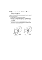
... Turn on the back of the connector. Be sure to the printer using an interface cable that matches the printer's specification. 1). Plug the drawer cable into the printer's interface connector, then tighten the screws on both the printer and the Host computer(POS/ECR). 2). Turn off both sides of... the printer and the Host computer(POS/ECR). otherwise the printer and the telephone line may be damaged 4). Connecting Interface Cable and Drawer Cable to the printer Connect the Host Computer(POS/ECR) to use a drawer that ...
... Turn on the back of the connector. Be sure to the printer using an interface cable that matches the printer's specification. 1). Plug the drawer cable into the printer's interface connector, then tighten the screws on both the printer and the Host computer(POS/ECR). 2). Turn off both sides of... the printer and the Host computer(POS/ECR). otherwise the printer and the telephone line may be damaged 4). Connecting Interface Cable and Drawer Cable to the printer Connect the Host Computer(POS/ECR) to use a drawer that ...
Operation Manual
Page 8
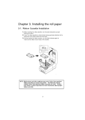
... are used . Installing the roll paper 3-1. Before inserting the ribbon cassette, turn the knob clockwise again to make sure the ribbon moves freely in the printer. Chapter 3. The Warranty may arise if other than specified ribbon cassettes are used in the cassette. Insert the ribbon cassette as shown below and pay...
... are used . Installing the roll paper 3-1. Before inserting the ribbon cassette, turn the knob clockwise again to make sure the ribbon moves freely in the printer. Chapter 3. The Warranty may arise if other than specified ribbon cassettes are used in the cassette. Insert the ribbon cassette as shown below and pay...
Operation Manual
Page 9
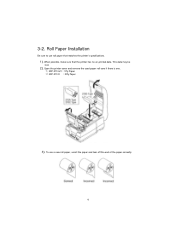
Roll Paper Installation Be sure to use a new roll paper, unroll the paper and tear off the end of the paper correctly. 9 Open the printer cover and remove the used paper roll core if there is one. " SRP-270 A/C : 1Ply Paper # SRP-270 D : 2Ply Paper 3). When possible, make sure that matches the printer's specifications. 1). To use roll paper that the printer has no un-printed data. This data may be lost. 2). 3-2.
Roll Paper Installation Be sure to use a new roll paper, unroll the paper and tear off the end of the paper correctly. 9 Open the printer cover and remove the used paper roll core if there is one. " SRP-270 A/C : 1Ply Paper # SRP-270 D : 2Ply Paper 3). When possible, make sure that matches the printer's specifications. 1). To use roll paper that the printer has no un-printed data. This data may be lost. 2). 3-2.
Operation Manual
Page 10
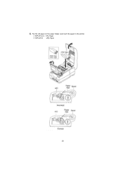
" SRP-270 A/C : 1Ply Paper # SRP-270 D : 2Ply Paper 10 4). Put the roll paper on the paper holder and insert the paper in the printer.
" SRP-270 A/C : 1Ply Paper # SRP-270 D : 2Ply Paper 10 4). Put the roll paper on the paper holder and insert the paper in the printer.
Operation Manual
Page 11
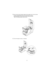
The printer feeds the paper automatically and then the printer will cut the paper automatically(SRP-270C type series and SRP-270D type series). Tear off the paper as shown, if necessary. 11 5) Insert the end of the roll paper straight into the paper inlet. Refer to the attached label inside the cover. 6).
The printer feeds the paper automatically and then the printer will cut the paper automatically(SRP-270C type series and SRP-270D type series). Tear off the paper as shown, if necessary. 11 5) Insert the end of the roll paper straight into the paper inlet. Refer to the attached label inside the cover. 6).
Operation Manual
Page 12
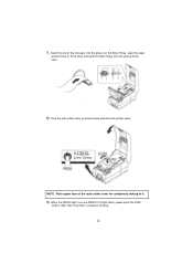
Insert the end of the Case. 8). Push the auto-cutter cover as shown below and close the printer cover. After that, the printer is on the Roller-Pulley, warp the paper around it . 9). 7). NOTE : Push upper face of it two or three times and load the Roller-Pulley onto the groove of the roll paper into the groove on and PAPER OUT light blinks, please press the FEED button. When the ERROR light is ready for completely locking of the auto cutter cover for printing. 12
Insert the end of the Case. 8). Push the auto-cutter cover as shown below and close the printer cover. After that, the printer is on the Roller-Pulley, warp the paper around it . 9). 7). NOTE : Push upper face of it two or three times and load the Roller-Pulley onto the groove of the roll paper into the groove on and PAPER OUT light blinks, please press the FEED button. When the ERROR light is ready for completely locking of the auto cutter cover for printing. 12
Operation Manual
Page 13
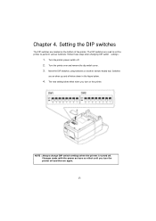
... narrow-ended tool. NOTE : Always change DIP switch settings when the printer is turned off . 2. Chapter 4. Turn the printer power switch off . Switches are on when up and off and then on have no effect until you turn the printer off when down in the figure below. 4. Changes made with the ...power on again. 13 Setting the DIP switches The DIP switches are used to set the printer to perform various functions. Follow these steps when changing DIP switch settings : 1. The new setting takes effect when you turn on the bottom of ...
... narrow-ended tool. NOTE : Always change DIP switch settings when the printer is turned off . 2. Chapter 4. Turn the printer power switch off . Switches are on when up and off and then on have no effect until you turn the printer off when down in the figure below. 4. Changes made with the ...power on again. 13 Setting the DIP switches The DIP switches are used to set the printer to perform various functions. Follow these steps when changing DIP switch settings : 1. The new setting takes effect when you turn on the bottom of ...
Operation Manual
Page 16
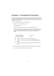
... Set DIP switch 2-2 On. 3. l Insufficient print data to the printer. When the printing finishes, turn on the printer, then the printer enters the hexadecimal dump mode. 4. Turn on the hexadecimal dump function, the printer prints all commands and data in a two-column format. Hexadecimal Dumping...by pressing the feed button. 5. After you find specific commands. Chapter 5. B . C l A period(.) is printed for each code that the printer is off . 2. l During the hex dump, all the codes it receives in hexadecimal format along with a guide section to the codes. 1B...
... Set DIP switch 2-2 On. 3. l Insufficient print data to the printer. When the printing finishes, turn on the printer, then the printer enters the hexadecimal dump mode. 4. Turn on the hexadecimal dump function, the printer prints all commands and data in a two-column format. Hexadecimal Dumping...by pressing the feed button. 5. After you find specific commands. Chapter 5. B . C l A period(.) is printed for each code that the printer is off . 2. l During the hex dump, all the codes it receives in hexadecimal format along with a guide section to the codes. 1B...
Operation Manual
Page 17
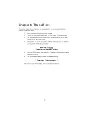
.... 1. Turn on the power while holding down the FEED button. Press the FEED button to receive data when it completes the self-test. 17 The printer prints a pattern using the built-in character set. 6. Please press the FEED button 5. Make sure paper roll has been installed properly. 2. The self-test begins.... 3. The self-test automatically ends after printing the following , and pause (The PAPER LED light blinks). The self-test prints the current printer status, which provides the control ROM version and the DIP switch setting. 4. After printing the current...
.... 1. Turn on the power while holding down the FEED button. Press the FEED button to receive data when it completes the self-test. 17 The printer prints a pattern using the built-in character set. 6. Please press the FEED button 5. Make sure paper roll has been installed properly. 2. The self-test begins.... 3. The self-test automatically ends after printing the following , and pause (The PAPER LED light blinks). The self-test prints the current printer status, which provides the control ROM version and the DIP switch setting. 4. After printing the current...
Operation Manual
Page 25
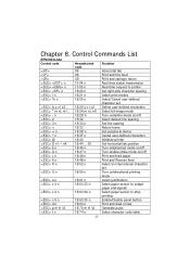
... t1 t2 1B 74 n Function Horizontal tab Print and line feed Print and carriage return Real-time status transmission Real-time request to printer Set right-side character spacing Select print modes Select/Cancel user-defined character set Define user-defined characters Select bit-image mode Turn underline ...mode on/off Select default line spacing Set line spacing Return home Set peripheral device Cancel user-defined characters Initialize printer Set horizontal tab position Turn emphasized mode on/off Turn double-strike mode on/off Print and feed paper Print and Reverse feed...
... t1 t2 1B 74 n Function Horizontal tab Print and line feed Print and carriage return Real-time status transmission Real-time request to printer Set right-side character spacing Select print modes Select/Cancel user-defined character set Define user-defined characters Select bit-image mode Turn underline ...mode on/off Select default line spacing Set line spacing Return home Set peripheral device Cancel user-defined characters Initialize printer Set horizontal tab position Turn emphasized mode on/off Turn double-strike mode on/off Print and feed paper Print and Reverse feed...
Operation Manual
Page 26
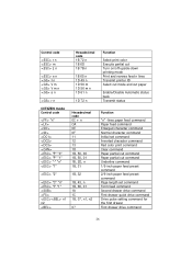
... 1B, 07, n1, n2 07 Function Select print color Execute partial cut Turn on/off upside-down printing mode Print and reverse feed n lines Transmit printer ID Select cut mode and cut paper Enable/Disable Automatic status back Transmit status Function "n" -lines paper feed command Paper feed command Enlarged character command...
... 1B, 07, n1, n2 07 Function Select print color Execute partial cut Turn on/off upside-down printing mode Print and reverse feed n lines Transmit printer ID Select cut mode and cut paper Enable/Disable Automatic status back Transmit status Function "n" -lines paper feed command Paper feed command Enlarged character command...
Operation Manual
Page 27
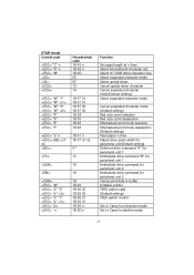
... n 1B 2D n Function Set page length at n lines Select international character set. Select 9×7(Half dots) character size Select expanded character mode Select upside-down Cancel upside-down character Cancel expanded character mode(Default setting...1 Immediate drive command "B" for peripheral unit 1 Immediate drive command for peripheral unit 2 Immediate drive command for peripheral unit 2 Cancel print data in buffer Initialize printer FEED switch valid (Default setting) FEED switch invalid Set or Cancel uni-direction mode Set or Cancel underline mode 27 STAR mode Control code "C" n "R" ...
... n 1B 2D n Function Set page length at n lines Select international character set. Select 9×7(Half dots) character size Select expanded character mode Select upside-down Cancel upside-down character Cancel expanded character mode(Default setting...1 Immediate drive command "B" for peripheral unit 1 Immediate drive command for peripheral unit 2 Immediate drive command for peripheral unit 2 Cancel print data in buffer Initialize printer FEED switch valid (Default setting) FEED switch invalid Set or Cancel uni-direction mode Set or Cancel underline mode 27 STAR mode Control code "C" n "R" ...
Operation Manual
Page 30
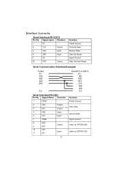
... 6 DSR Input 7 SG - 20 DTR Output Function Frame Ground Transmit Data Receive Data Data Set Ready Signal Ground Data Terminal Ready Serial Communication Interface(Example) Printer SG TXD RSD DSR DTR S.G Host(DTE ex 8251) SG TXD RSD RTS CTS DSR DTR S.G Serial Interface(RS-485) Pin No.
... 6 DSR Input 7 SG - 20 DTR Output Function Frame Ground Transmit Data Receive Data Data Set Ready Signal Ground Data Terminal Ready Serial Communication Interface(Example) Printer SG TXD RSD DSR DTR S.G Host(DTE ex 8251) SG TXD RSD RTS CTS DSR DTR S.G Serial Interface(RS-485) Pin No.

Operation Manual
Page 31
... Compatibility Mode 1 Host nStrobe 2 Host / Printer Data 0 (LSB) 3 Host / Printer Data 1 4 Host / Printer Data 2 5 Host / Printer Data 3 6 Host / Printer Data 4 7 Host / Printer Data 5 8 Host / Printer Data 6 9 Host / Printer Data 7 (MSB) 10 Printer nAck 11 Printer Busy 12 Printer Perror 13 14 15 16 17 18 19~30 31 32 33 34 35 36 Printer Host Printer Host Printer Printer Printer Host Select nAutoFd NC GND FG...
... Compatibility Mode 1 Host nStrobe 2 Host / Printer Data 0 (LSB) 3 Host / Printer Data 1 4 Host / Printer Data 2 5 Host / Printer Data 3 6 Host / Printer Data 4 7 Host / Printer Data 5 8 Host / Printer Data 6 9 Host / Printer Data 7 (MSB) 10 Printer nAck 11 Printer Busy 12 Printer Perror 13 14 15 16 17 18 19~30 31 32 33 34 35 36 Printer Host Printer Host Printer Printer Printer Host Select nAutoFd NC GND FG...