User Guide
Page 2
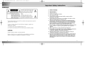
...service personnel. When a cart is subject to rain or moisture, does not operate normally, or been dropped. 3 This symbol indicates high voltage is incorrectly replaced. This symbol alerts you that important literature concerning operation and maintenance has been included with one wider than the other...been damaged in accordance with the apparatus. NO USER SERVICEABLE PARTS INSIDE. Do not install near water. 6. Clean only with part 15 of contact with the same or equivalent type recommended by the manufacturer. 12. 00326A SCC-931T(P)-eng 9/25/02 12:30 PM Page 2 CAUTION RISK...
...service personnel. When a cart is subject to rain or moisture, does not operate normally, or been dropped. 3 This symbol indicates high voltage is incorrectly replaced. This symbol alerts you that important literature concerning operation and maintenance has been included with one wider than the other...been damaged in accordance with the apparatus. NO USER SERVICEABLE PARTS INSIDE. Do not install near water. 6. Clean only with part 15 of contact with the same or equivalent type recommended by the manufacturer. 12. 00326A SCC-931T(P)-eng 9/25/02 12:30 PM Page 2 CAUTION RISK...
User Guide
Page 3
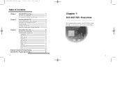
... Contents Chapter 1 SCC-931T(P) Overview 5 SCC-931T(P) Introduction 6 SCC-931T(P) Part Names and Functions 7 Chapter 2 Installing SCC-931T(P) 9 Checking the Contents of the Package 10 Precautions for Installation and Use 12 Preparing Cables 14 Installing SCC-931T(P) 15 Connecting Cables and Checking Operations 22 Chapter 3 Setup Menu Overview 24 Structure of the Setup Menu 25 CAMERA MENU Organization 26 CAMERA ID 26 IRIS...
... Contents Chapter 1 SCC-931T(P) Overview 5 SCC-931T(P) Introduction 6 SCC-931T(P) Part Names and Functions 7 Chapter 2 Installing SCC-931T(P) 9 Checking the Contents of the Package 10 Precautions for Installation and Use 12 Preparing Cables 14 Installing SCC-931T(P) 15 Connecting Cables and Checking Operations 22 Chapter 3 Setup Menu Overview 24 Structure of the Setup Menu 25 CAMERA MENU Organization 26 CAMERA ID 26 IRIS...
User Guide
Page 4
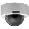
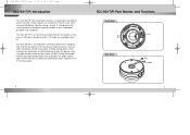
... that enables shooting moving subject. 00326A SCC-931T(P)-eng 9/25/02 12:30 PM Page 6 SCC-931T(P) Introduction The SCC-931T(P) Anti-Vandal Dome Camera is waterproof, dustproof, and shockproof. SCC-931T(P) Part Names and Functions Front View Rear View BNC POWER 6 7 It is designed to withstand intentional or accidental impact or vandalism, and is a dome-typed surveillance device that offers the best...
... that enables shooting moving subject. 00326A SCC-931T(P)-eng 9/25/02 12:30 PM Page 6 SCC-931T(P) Introduction The SCC-931T(P) Anti-Vandal Dome Camera is waterproof, dustproof, and shockproof. SCC-931T(P) Part Names and Functions Front View Rear View BNC POWER 6 7 It is designed to withstand intentional or accidental impact or vandalism, and is a dome-typed surveillance device that offers the best...
User Guide
Page 5
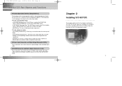
Now, let's install the SCC-931T(P) and connect cables. 9 00326A SCC-931T(P)-eng 9/25/02 12:30 PM Page 8 SCC-931T(P) Part Names and Functions ❶ Camera Operation Switches (Setup Switches) The functions of the camera operation switches change depending on whether the SCC-931T(P) is currently in the usual operation mode ... for transmitting the ALARM signal at the time of the MOTION DET mode. 8 Chapter 2 Installing SCC-931T(P) This chapter explains what to check before installing the SCC-931T(P), how to choose an installation site, and what precautions should be taken during installation.
Now, let's install the SCC-931T(P) and connect cables. 9 00326A SCC-931T(P)-eng 9/25/02 12:30 PM Page 8 SCC-931T(P) Part Names and Functions ❶ Camera Operation Switches (Setup Switches) The functions of the camera operation switches change depending on whether the SCC-931T(P) is currently in the usual operation mode ... for transmitting the ALARM signal at the time of the MOTION DET mode. 8 Chapter 2 Installing SCC-931T(P) This chapter explains what to check before installing the SCC-931T(P), how to choose an installation site, and what precautions should be taken during installation.

User Guide
Page 12
First connect one part of the power adapter consisting of two lines to the power input ...) 22 4. Data Bit Number: 8 bits - Next, connect the other end of the BNC cable to connect one end of the SCC-931T(P) as follows. (GND: marked with a white line on the type of power source you want to the VIDEO OUT. 2. Communication ...Speed: 4800 bps ~ 38400 bps - If the camera operates normally, the following : - Stop Bit Number: 1 bit - Then, plug the power adapter into the power receptacle. 5. ADDR:0 ...
First connect one part of the power adapter consisting of two lines to the power input ...) 22 4. Data Bit Number: 8 bits - Next, connect the other end of the BNC cable to connect one end of the SCC-931T(P) as follows. (GND: marked with a white line on the type of power source you want to the VIDEO OUT. 2. Communication ...Speed: 4800 bps ~ 38400 bps - If the camera operates normally, the following : - Stop Bit Number: 1 bit - Then, plug the power adapter into the power receptacle. 5. ADDR:0 ...

User Guide
Page 22
... Aperture : F1.8(Wide), F2.6(Tele) RS485 (Half Duplex) -10°C ~ +50°C (14°F~122°F) ~90% 132(ø) x 95.3 mm Approx. 1kg/2.2lb 42 Part No. AB68-00326A (01) Printed in Korea 00326A SCC-931T(P)-eng 9/25/02 12:30 PM Page 42...
... Aperture : F1.8(Wide), F2.6(Tele) RS485 (Half Duplex) -10°C ~ +50°C (14°F~122°F) ~90% 132(ø) x 95.3 mm Approx. 1kg/2.2lb 42 Part No. AB68-00326A (01) Printed in Korea 00326A SCC-931T(P)-eng 9/25/02 12:30 PM Page 42...