User Guide
Page 2
..., does not operate normally, or been dropped. 3 Use only with cart, stand, tripod, bracket, or table specified by the manufacturer, or sold with any kind of the FCC Rules. This symbol indicates high voltage is incorrectly replaced. CAUTION: Danger of explosion if battery is present inside part of used batteries according to qualified service personnel. Replace only with this...
..., does not operate normally, or been dropped. 3 Use only with cart, stand, tripod, bracket, or table specified by the manufacturer, or sold with any kind of the FCC Rules. This symbol indicates high voltage is incorrectly replaced. CAUTION: Danger of explosion if battery is present inside part of used batteries according to qualified service personnel. Replace only with this...
User Guide
Page 3
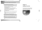
... Functions 7 Chapter 2 Installing SCC-931T(P) 9 Checking the Contents of the Package 10 Precautions for Installation and Use 12 Preparing Cables 14 Installing SCC-931T(P) 15 Connecting Cables and Checking Operations 22 Chapter 3 Setup Menu Overview 24 Structure of the Setup Menu 25 CAMERA MENU Organization 26 CAMERA ID 26 IRIS 26 AUTO FOCUS 29 SHUTTER 30 AGC/MOTION 31 WHITE BAL 32 SYNC 34 SPECIAL 34 MOTION DET 38 EXIT 39 External Connector Pin Specifications 40 SCC-931T(P) -
... Functions 7 Chapter 2 Installing SCC-931T(P) 9 Checking the Contents of the Package 10 Precautions for Installation and Use 12 Preparing Cables 14 Installing SCC-931T(P) 15 Connecting Cables and Checking Operations 22 Chapter 3 Setup Menu Overview 24 Structure of the Setup Menu 25 CAMERA MENU Organization 26 CAMERA ID 26 IRIS 26 AUTO FOCUS 29 SHUTTER 30 AGC/MOTION 31 WHITE BAL 32 SYNC 34 SPECIAL 34 MOTION DET 38 EXIT 39 External Connector Pin Specifications 40 SCC-931T(P) -
User Guide
Page 4
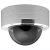
... locations with bright incident light, and the Auto Focus function that automatically tracks and focuses on the moving subject. SCC-931T(P) Part Names and Functions Front View Rear View BNC POWER 6 7 It is designed to withstand intentional or accidental impact or vandalism, and is equipped with its 12x zoom lens and digital zoom IC. The SCC-931T(P) is a multifunction surveillance device that enables a maximum of 120x zoom surveillance with all of...
... locations with bright incident light, and the Auto Focus function that automatically tracks and focuses on the moving subject. SCC-931T(P) Part Names and Functions Front View Rear View BNC POWER 6 7 It is designed to withstand intentional or accidental impact or vandalism, and is equipped with its 12x zoom lens and digital zoom IC. The SCC-931T(P) is a multifunction surveillance device that enables a maximum of 120x zoom surveillance with all of...
User Guide
Page 5
... Video Output Connector (5-Pin) These connectors are used to connect the power adapter cable and video input cable. ❸ RS485 Connector and Alarm Output Connector (4-Pin) These connectors are used to connect an RS485 remote control cable and a cable used for transmitting the ALARM signal at the time of the MOTION DET mode. 8 Chapter 2 Installing SCC-931T(P) This chapter explains what to check before installing the SCC-931T(P), how to choose an installation site, and what precautions should be taken during installation. Now, let's install the SCC-931T...
... Video Output Connector (5-Pin) These connectors are used to connect the power adapter cable and video input cable. ❸ RS485 Connector and Alarm Output Connector (4-Pin) These connectors are used to connect an RS485 remote control cable and a cable used for transmitting the ALARM signal at the time of the MOTION DET mode. 8 Chapter 2 Installing SCC-931T(P) This chapter explains what to check before installing the SCC-931T(P), how to choose an installation site, and what precautions should be taken during installation. Now, let's install the SCC-931T...

User Guide
Page 6
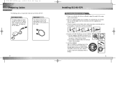
SCC-931T(P) User's Guide User's Guide ALARM & RS485 Cable 10 ✔ PLASTIC ANCHOR 2 ea. ❙ for ceiling installation ✔ ASSY SCREW TAPPING 2 ea. ❙ for ceiling installation (TH M4 X L30 BLK + 0 RING) ✔ ASSY SCREW MACHINE 2 ea. ❙ Attach to check that the following items are included in the package. 00326A SCC-931T(P)-eng 9/25/02 12:30 PM Page 10 Before Installation Checking...
SCC-931T(P) User's Guide User's Guide ALARM & RS485 Cable 10 ✔ PLASTIC ANCHOR 2 ea. ❙ for ceiling installation ✔ ASSY SCREW TAPPING 2 ea. ❙ for ceiling installation (TH M4 X L30 BLK + 0 RING) ✔ ASSY SCREW MACHINE 2 ea. ❙ Attach to check that the following items are included in the package. 00326A SCC-931T(P)-eng 9/25/02 12:30 PM Page 10 Before Installation Checking...

User Guide
Page 7
... the cable is not removed. (Neglecting to do so may cause fire or damage to the product.) ✔ Prevent people from approaching the installation area, where objects might fall during use or storage. Operating Temperature: -10°C ~ +50°C (14°F~122°F) - Use the BLC function when operating the SCC-931T(P) underneath a spot light or under very bright lights. ✔ Use...
... the cable is not removed. (Neglecting to do so may cause fire or damage to the product.) ✔ Prevent people from approaching the installation area, where objects might fall during use or storage. Operating Temperature: -10°C ~ +50°C (14°F~122°F) - Use the BLC function when operating the SCC-931T(P) underneath a spot light or under very bright lights. ✔ Use...
User Guide
Page 8
... when installing the CAMERA. 4. Power Adapter Cable The power adapter that connects the video output terminal of the SCC-931T(P) to install and use the SCC-931T(P). Choose an installation site that they will not be installed. 2. Video Cable The cable that plugs into the SCC-931T(P)'s power input receptacle has the rated voltage of the equipments to the installation site, drill pilot holes (5 mm diam eter, min. 35 mm depth), and then install and secure the supplied plastic...
... when installing the CAMERA. 4. Power Adapter Cable The power adapter that connects the video output terminal of the SCC-931T(P) to install and use the SCC-931T(P). Choose an installation site that they will not be installed. 2. Video Cable The cable that plugs into the SCC-931T(P)'s power input receptacle has the rated voltage of the equipments to the installation site, drill pilot holes (5 mm diam eter, min. 35 mm depth), and then install and secure the supplied plastic...

User Guide
Page 9
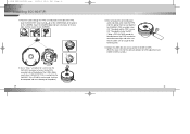
... when installing indoor.) 4. SCREW 2. After assembling the DOME COVER in the desired direction, hold the COVER- For installing on a pipe 1. Connect the power cable and video cable. 5. After arranging the connected power cable and video cable inside wiring LENS LENS BODY and cause damage such as shown in the illustration to move the LENS body and COVER LENS. 2) Move the LENS body to adjust the vertical direction and turn the LENS body...
... when installing indoor.) 4. SCREW 2. After assembling the DOME COVER in the desired direction, hold the COVER- For installing on a pipe 1. Connect the power cable and video cable. 5. After arranging the connected power cable and video cable inside wiring LENS LENS BODY and cause damage such as shown in the illustration to move the LENS body and COVER LENS. 2) Move the LENS body to adjust the vertical direction and turn the LENS body...

User Guide
Page 10
...; Disconnect the CONNECTOR from the PCB. Through the center hole of the PCB, remove the cable from the cable fixing clip. Remove the cable from the CAMERA. Adjust the LENS direction and assemble the DOME COVER. (Refer the steps 6 to 8 of the ceiling installation for fixing the CAMERA body by turning them counter- Remove the DOME COVER to adjust the LENS 1) 2) direction. 1) Use the supplied L WRENCH...
...; Disconnect the CONNECTOR from the PCB. Through the center hole of the PCB, remove the cable from the cable fixing clip. Remove the cable from the CAMERA. Adjust the LENS direction and assemble the DOME COVER. (Refer the steps 6 to 8 of the ceiling installation for fixing the CAMERA body by turning them counter- Remove the DOME COVER to adjust the LENS 1) 2) direction. 1) Use the supplied L WRENCH...
User Guide
Page 11
... of the ceiling installation for LENS adjustment and DOME COVER assembly.) 21 00326A SCC-931T(P)-eng 9/25/02 12:30 PM Page 20 Installing SCC-931T(P) 7) Route the cables through the PIPE assembly hole on the side of the PIPE, align the INDEX KEY arrow mark ( ) of the CAMERA body to the groove on the CAMERA, mount the CAMERA body and turn it clockwise all...
... of the ceiling installation for LENS adjustment and DOME COVER assembly.) 21 00326A SCC-931T(P)-eng 9/25/02 12:30 PM Page 20 Installing SCC-931T(P) 7) Route the cables through the PIPE assembly hole on the side of the PIPE, align the INDEX KEY arrow mark ( ) of the CAMERA body to the groove on the CAMERA, mount the CAMERA body and turn it clockwise all...

User Guide
Page 12
... then adjust the power selection switch located at the bottom of the monitor. 3. Then, plug the power adapter into the power receptacle. 5. Then, plug in the power adapter. When controlling an RS485, please check the following screen will be displayed for 5 seconds before it disappears. Parity Bit: None 23 00326A SCC-931T(P)-eng 9/25/02 12:30 PM Page 22 Connecting Cables and Checking Operations 1. First connect one part of the power adapter...
... then adjust the power selection switch located at the bottom of the monitor. 3. Then, plug the power adapter into the power receptacle. 5. Then, plug in the power adapter. When controlling an RS485, please check the following screen will be displayed for 5 seconds before it disappears. Parity Bit: None 23 00326A SCC-931T(P)-eng 9/25/02 12:30 PM Page 22 Connecting Cables and Checking Operations 1. First connect one part of the power adapter...

User Guide
Page 13
... WHITE BAL ATW/AWC/MENU... MENU... MOTION DET ON.../OFF ON... AUTOFOCUS AF/ONEAF/MF SHUTTER OFF/1/100~1/10K OFF/AUTO X2~X128 OFF/FIX X2~X128 MENU... SYNC INT/LINE... SPECIAL ... ON... ALC... LINE... EXIT QUIT/SAVE/PRESET CAMERA ID SETUP CAMERA ID POSITION SETUP AREA SETUP BLC SETUP LEVEL SETUP LEVEL SETUP 3200K/5600K/USER RED, BLUE SETUP PHASE SETUP RS485, PRESET D-ZOOM, PIP, MIRROR, POSI/NEGA ZOOM SPEED DETAIL SETUP AREA SETUP...
... WHITE BAL ATW/AWC/MENU... MENU... MOTION DET ON.../OFF ON... AUTOFOCUS AF/ONEAF/MF SHUTTER OFF/1/100~1/10K OFF/AUTO X2~X128 OFF/FIX X2~X128 MENU... SYNC INT/LINE... SPECIAL ... ON... ALC... LINE... EXIT QUIT/SAVE/PRESET CAMERA ID SETUP CAMERA ID POSITION SETUP AREA SETUP BLC SETUP LEVEL SETUP LEVEL SETUP 3200K/5600K/USER RED, BLUE SETUP PHASE SETUP RS485, PRESET D-ZOOM, PIP, MIRROR, POSI/NEGA ZOOM SPEED DETAIL SETUP AREA SETUP...
User Guide
Page 14
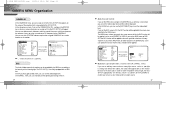
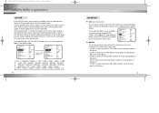
CAMERA ID IRIS AUTO FOCUS SHUTTER MOTION WHITE BAL SYNC SPECIAL MOTION DET EXIT ON... OFF QUIT When you press the [ENTER] key (ALC) AREA BLC LEVEL(0) RET PRESET... RET SCC-931T.... ☛ "..." means that appears on the monitor because of the incoming light. menu, you can manually set the opening and closing of back light, the SCC931T(P) appropriately sets the BLC, which is connected to the SCC-931T(P). OFF...
CAMERA ID IRIS AUTO FOCUS SHUTTER MOTION WHITE BAL SYNC SPECIAL MOTION DET EXIT ON... OFF QUIT When you press the [ENTER] key (ALC) AREA BLC LEVEL(0) RET PRESET... RET SCC-931T.... ☛ "..." means that appears on the monitor because of the incoming light. menu, you can manually set the opening and closing of back light, the SCC931T(P) appropriately sets the BLC, which is connected to the SCC-931T(P). OFF...

User Guide
Page 15
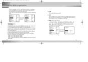
... (Manual Focus) The user can manually adjust the focus with the AUTO FOCUS MODE. This is same as the MF Mode while the SCC-931T(P) is stopped and same as the AF Mode while it is pressed. ALC... You can set the Focus to ONEAF, AF, or MF. ➼ AF (Auto Focus) Automatically FOCUSes by pressing the [LEFT, RIGHT, TOP, BOTTOM] keys. CAMERA ID IRIS AUTO FOCUS SHUTTER MOTION WHITE BAL SYNC SPECIAL MOTION...
... (Manual Focus) The user can manually adjust the focus with the AUTO FOCUS MODE. This is same as the MF Mode while the SCC-931T(P) is stopped and same as the AF Mode while it is pressed. ALC... You can set the Focus to ONEAF, AF, or MF. ➼ AF (Auto Focus) Automatically FOCUSes by pressing the [LEFT, RIGHT, TOP, BOTTOM] keys. CAMERA ID IRIS AUTO FOCUS SHUTTER MOTION WHITE BAL SYNC SPECIAL MOTION...
User Guide
Page 16
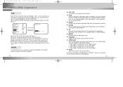
... setting to monitor moving objects in dark places. - The high-speed electronic shutter supports 7 shutter speeds from 1/100 seconds to 1/10K seconds, and the AUTO low-speed shutter and the FIX low-speed shutter support 12 shutter speeds from 2x to monitor very fast moving objects in the following order: CAMERA ID IRIS AUTO FOCUS SHUTTER MOTION WHITE BAL SYNC SPECIAL MOTION DET EXIT OFF... F. OFF QUIT Using the...
... setting to monitor moving objects in dark places. - The high-speed electronic shutter supports 7 shutter speeds from 1/100 seconds to 1/10K seconds, and the AUTO low-speed shutter and the FIX low-speed shutter support 12 shutter speeds from 2x to monitor very fast moving objects in the following order: CAMERA ID IRIS AUTO FOCUS SHUTTER MOTION WHITE BAL SYNC SPECIAL MOTION DET EXIT OFF... F. OFF QUIT Using the...
User Guide
Page 17
... you set the WHITE BAL menu to the MANUAL mode, the user can select the Manual White Balance will continuously monitor changes in front of any color temperature. OFF QUIT Using the [LEFT, RIGHT] keys CAMERA ID IRIS AUTO FOCUS SHUTTER MOTION WHITE BAL SYNC SPECIAL MOTION DET EXIT OFF... item and press the [ENTER] key, a MANU... ALC... If you can set to the low illumination mode in the PRESET menu. USER: sets the color...
... you set the WHITE BAL menu to the MANUAL mode, the user can select the Manual White Balance will continuously monitor changes in front of any color temperature. OFF QUIT Using the [LEFT, RIGHT] keys CAMERA ID IRIS AUTO FOCUS SHUTTER MOTION WHITE BAL SYNC SPECIAL MOTION DET EXIT OFF... item and press the [ENTER] key, a MANU... ALC... If you can set to the low illumination mode in the PRESET menu. USER: sets the color...
User Guide
Page 18
... when using a multiple number of cameras, each CAMERA set between each must use the [LEFT/RIGHT] keys to x12 Fastest speed ➼ DETAIL Adjusts the horizontal and vertical sharpness. If the D-ZOOM is not used , communication may not be displayed. ➼ MIRROR Horizontally flips the video output signal. ➼ POSI/NEGA Outputs the video output signal normally or inversely. ➼ ZOOM SPEED Sets the Zoom speed. Position the cursor on the SCC-931T(P). ➼...
... when using a multiple number of cameras, each CAMERA set between each must use the [LEFT/RIGHT] keys to x12 Fastest speed ➼ DETAIL Adjusts the horizontal and vertical sharpness. If the D-ZOOM is not used , communication may not be displayed. ➼ MIRROR Horizontally flips the video output signal. ➼ POSI/NEGA Outputs the video output signal normally or inversely. ➼ ZOOM SPEED Sets the Zoom speed. Position the cursor on the SCC-931T(P). ➼...

User Guide
Page 19
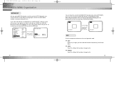
... RS485 menu, you press the [ENTER] key (PRESET MAP) 0* 1 2 3 4 5 6 789 RET ID:PRESET0 36 You can set the desired item. RS485 ... 00326A SCC-931T(P)-eng 9/25/02 12:30 PM Page 36 CAMERA MENU Organization CAMERA ID IRIS AUTO FOCUS SHUTTER MOTION WHITE BAL SYNC SPECIAL MOTION DET EXIT OFF... item and press the [ENTER] key, you press the [ENTER] key PRESET NO. 0 POSITION SET PRESET ID...
... RS485 menu, you press the [ENTER] key (PRESET MAP) 0* 1 2 3 4 5 6 789 RET ID:PRESET0 36 You can set the desired item. RS485 ... 00326A SCC-931T(P)-eng 9/25/02 12:30 PM Page 36 CAMERA MENU Organization CAMERA ID IRIS AUTO FOCUS SHUTTER MOTION WHITE BAL SYNC SPECIAL MOTION DET EXIT OFF... item and press the [ENTER] key, you press the [ENTER] key PRESET NO. 0 POSITION SET PRESET ID...
User Guide
Page 20
.... AF AUTO X8 F.FAST ATW INT ... MEDIUM 38 You can move the cursor to the SENSITIVITY position and use the [LEFT/RIGHT] keys to the previous MOTION DET MENU. 00326A SCC-931T(P)-eng 9/25/02 12:30 PM Page 38 CAMERA MENU Organization MOTION DET You can set the sensitivity for MOTION detection (LOW, MEDIUM, HIGH). If you have made and restores the previously saved setup menu...
.... AF AUTO X8 F.FAST ATW INT ... MEDIUM 38 You can move the cursor to the SENSITIVITY position and use the [LEFT/RIGHT] keys to the previous MOTION DET MENU. 00326A SCC-931T(P)-eng 9/25/02 12:30 PM Page 38 CAMERA MENU Organization MOTION DET You can set the sensitivity for MOTION detection (LOW, MEDIUM, HIGH). If you have made and restores the previously saved setup menu...

User Guide
Page 22
AB68-00326A (01) Printed in Korea Product Specifications ITEM Back Light Compensation Sense Up Digital Zoom Motion Detection Video Control Signal Output Lens Remote Control Operating Temperature Operating Humidity Physical Size Weight DESCRIPTION Off/On (Area Setting) Off/Auto 2x~28x/Fix 2x~128x Off/On(x10), PIP Off/On (Area/Sensitivity Setting) POSI/NEGA, MIRROR, Detail Setting Composite Video Out : 1.0 Vp-p 75 ohms/BNC Focal length : 3.6 ~ 43.2 mm Aperture...
AB68-00326A (01) Printed in Korea Product Specifications ITEM Back Light Compensation Sense Up Digital Zoom Motion Detection Video Control Signal Output Lens Remote Control Operating Temperature Operating Humidity Physical Size Weight DESCRIPTION Off/On (Area Setting) Off/Auto 2x~28x/Fix 2x~128x Off/On(x10), PIP Off/On (Area/Sensitivity Setting) POSI/NEGA, MIRROR, Detail Setting Composite Video Out : 1.0 Vp-p 75 ohms/BNC Focal length : 3.6 ~ 43.2 mm Aperture...


