
Owners Instructions
Page 2
...; Cell Defects The PDP Display uses a panel consisting of the product. © 2007 Samsung Electronics Co., Ltd. All rights reserved. BN68-01304A-00Eng 5/31/07 3:49 PM Page 2 User Instructions ◆ Screen Image retention Do not display a still image (such as on a video game or when hooking up a PC to this effect, reduce the 'brightness' and 'contrast' when displaying still images for a long time. ◆ Warranty - It...
...; Cell Defects The PDP Display uses a panel consisting of the product. © 2007 Samsung Electronics Co., Ltd. All rights reserved. BN68-01304A-00Eng 5/31/07 3:49 PM Page 2 User Instructions ◆ Screen Image retention Do not display a still image (such as on a video game or when hooking up a PC to this effect, reduce the 'brightness' and 'contrast' when displaying still images for a long time. ◆ Warranty - It...
Owners Instructions
Page 4
... PM Page 4 Contents ◆ FOREWORD ■ User Instructions 2 ◆ CONNECTING AND PREPARING YOUR DISPLAY ■ Control Panel 6 ■ Infrared Remote Control 8 ■ Inserting the Batteries in the Remote Control 9 ■ Assembling the Stand-Base 9 ■ Installing the Display on the Wall Attachment Panel 10 ■ Installing the Display Vertically 12 ■ Before Using the Video Wall and the Multiple Display Control function ........ 12 ■ Connecting Speakers 13 ■ Switching Your PDP Display On and Off 15 ■ Choosing Your...
... PM Page 4 Contents ◆ FOREWORD ■ User Instructions 2 ◆ CONNECTING AND PREPARING YOUR DISPLAY ■ Control Panel 6 ■ Infrared Remote Control 8 ■ Inserting the Batteries in the Remote Control 9 ■ Assembling the Stand-Base 9 ■ Installing the Display on the Wall Attachment Panel 10 ■ Installing the Display Vertically 12 ■ Before Using the Video Wall and the Multiple Display Control function ........ 12 ■ Connecting Speakers 13 ■ Switching Your PDP Display On and Off 15 ■ Choosing Your...
Owners Instructions
Page 5
... External Signal Source 38 ◆ ADDITIONAL INFORMATION AND CONNECTIONS ■ Connecting to the Audio/Video Input 39 ■ Connecting to the S-Video Input 40 ■ Connecting to the Component Input 40 ■ Connecting to the DVD/DTV Receiver Input 41 ■ Connecting to the DVI Input 41 ■ Connecting to the PC Input 42 ■ Setting up Your PC Software (Windows only 43 ■ Input Mode (PC/DVI 44 ■ Power Saver (PC1 mode only 45 ◆ RECOMMENDATIONS FOR USE ■ Troubleshooting...
... External Signal Source 38 ◆ ADDITIONAL INFORMATION AND CONNECTIONS ■ Connecting to the Audio/Video Input 39 ■ Connecting to the S-Video Input 40 ■ Connecting to the Component Input 40 ■ Connecting to the DVD/DTV Receiver Input 41 ■ Connecting to the DVI Input 41 ■ Connecting to the PC Input 42 ■ Setting up Your PC Software (Windows only 43 ■ Input Mode (PC/DVI 44 ■ Power Saver (PC1 mode only 45 ◆ RECOMMENDATIONS FOR USE ■ Troubleshooting...

Owners Instructions
Page 6
... 6 Control Panel ➢ The actual configuration of your PDP Display may be different, depending on your settings in the menu. - Select the external input source. - Power On; Green - When the Main menu is displayed on screen, the Main menu is in the menu. Adjust an option value respectively. (VOL + : Enter to switch on -screen menu. f) SEL ➢ Control the cursor in standby ➢ mode depending on the model. ◆ The VOL -, + and SEL , buttons have...
... 6 Control Panel ➢ The actual configuration of your PDP Display may be different, depending on your settings in the menu. - Select the external input source. - Power On; Green - When the Main menu is displayed on screen, the Main menu is in the menu. Adjust an option value respectively. (VOL + : Enter to switch on -screen menu. f) SEL ➢ Control the cursor in standby ➢ mode depending on the model. ◆ The VOL -, + and SEL , buttons have...

Owners Instructions
Page 7
... to Page 12. ➢ AUDIO is an audio input jack for component. English - 7 Connect external speakers. - j) S-VIDEO IN Video input for external devices, such as a camcorder or VCR. BN68-01304A-00Eng 6/25/07 2:47 PM Page 7 Rear Panel a) POWER IN g) RS-232C Connect the supplied power cord. - d) DVI IN Connect to the video output jack on external devices. OUT : Used for external devices. PC IN1 : Connect to the video output jack for detailed connection instructions and associated safety precautions...
... to Page 12. ➢ AUDIO is an audio input jack for component. English - 7 Connect external speakers. - j) S-VIDEO IN Video input for external devices, such as a camcorder or VCR. BN68-01304A-00Eng 6/25/07 2:47 PM Page 7 Rear Panel a) POWER IN g) RS-232C Connect the supplied power cord. - d) DVI IN Connect to the video output jack on external devices. OUT : Used for external devices. PC IN1 : Connect to the video output jack for detailed connection instructions and associated safety precautions...
Owners Instructions
Page 8
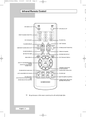
... TEMPORARY SOUND SWITCH-OFF VOLUME DECREASE SETTING THE TIMER MENU DISPLAY MOVE TO THE REQUIRED MENU OPTION/ ADJUST AN OPTION VALUE RESPECTIVELY PICTURE EFFECT SELECTION AUTO ADJUSTMENT IN PC MODE PIP FUNCTIONS: - SOURCE SELECTION (SOURCE) PDP DISPLAY OFF PICTURE STILL NEXT CHANNEL EXTERNAL INPUT SELECTION PREVIOUS CHANNEL INFORMATION DISPLAY EXIT FROM ANY DISPLAY CONFIRM YOUR CHOICE (STORE OR ENTER) SOUND EFFECT SELECTION PICTURE SIZE MULTIPLE DISPLAY CONTROL SCREEN EFFECT SELECTION (BURNING PROTECTION) ➢ ➢ The performance of the remote control may be affected by bright light...
... TEMPORARY SOUND SWITCH-OFF VOLUME DECREASE SETTING THE TIMER MENU DISPLAY MOVE TO THE REQUIRED MENU OPTION/ ADJUST AN OPTION VALUE RESPECTIVELY PICTURE EFFECT SELECTION AUTO ADJUSTMENT IN PC MODE PIP FUNCTIONS: - SOURCE SELECTION (SOURCE) PDP DISPLAY OFF PICTURE STILL NEXT CHANNEL EXTERNAL INPUT SELECTION PREVIOUS CHANNEL INFORMATION DISPLAY EXIT FROM ANY DISPLAY CONFIRM YOUR CHOICE (STORE OR ENTER) SOUND EFFECT SELECTION PICTURE SIZE MULTIPLE DISPLAY CONTROL SCREEN EFFECT SELECTION (BURNING PROTECTION) ➢ ➢ The performance of the remote control may be affected by bright light...
Owners Instructions
Page 11
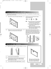
... securely hold the product to adjust the angle. Wall Bracket Wall 1 Fix the product to the wall bracket. 2 Hold the product at the top in step 2 (plastic hanger 4 Remove safety pin (#) and insert the 4 product + screw ) to the bracket. BN68-01304A-00Eng 5/31/07 3:49 PM Page 11 t. PDP Display Wall Bracket Angle Adjustment ➢ Adjust the bracket angle to -2o before installing it forward (direction of the...
... securely hold the product to adjust the angle. Wall Bracket Wall 1 Fix the product to the wall bracket. 2 Hold the product at the top in step 2 (plastic hanger 4 Remove safety pin (#) and insert the 4 product + screw ) to the bracket. BN68-01304A-00Eng 5/31/07 3:49 PM Page 11 t. PDP Display Wall Bracket Angle Adjustment ➢ Adjust the bracket angle to -2o before installing it forward (direction of the...
Owners Instructions
Page 12
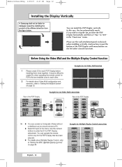
... PM Page 12 Installing the Display Vertically ❋ Samsung shall not be difficult to create IDs when operating the remote control for PDP Display adjustment. Example for 2x2 Video Wall connections Rear of the PDP Display ② ① ➢ ◆ You can install the PDP Display vertically. Please use the wall attachment panel exclusively when installing vertically. Use the numeric buttons to "Setting the MDC (Multiple Display Control)" on page 32. Before Using the Video Wall and the Multiple Display Control function 1 Please create...
... PM Page 12 Installing the Display Vertically ❋ Samsung shall not be difficult to create IDs when operating the remote control for PDP Display adjustment. Example for 2x2 Video Wall connections Rear of the PDP Display ② ① ➢ ◆ You can install the PDP Display vertically. Please use the wall attachment panel exclusively when installing vertically. Use the numeric buttons to "Setting the MDC (Multiple Display Control)" on page 32. Before Using the Video Wall and the Multiple Display Control function 1 Please create...
Owners Instructions
Page 19
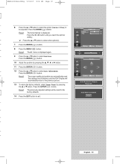
... all finished, and the PDP Display will be adjusted. Result: The previously adjusted settings will automatically return to select other option(s). 7 Press the ENTER ( ) button. 8 Press the MENU ( ) button. Result: The horizontal bar is displayed again. 9 Press the ... Press the ENTER ( ) button. or † button to be reset to the factory defaults. 14 Press the EXIT button to select Position. Image Lock Coarse 50 Fine 30 Move...
... all finished, and the PDP Display will be adjusted. Result: The previously adjusted settings will automatically return to select other option(s). 7 Press the ENTER ( ) button. 8 Press the MENU ( ) button. Result: The horizontal bar is displayed again. 9 Press the ... Press the ENTER ( ) button. or † button to be reset to the factory defaults. 14 Press the EXIT button to select Position. Image Lock Coarse 50 Fine 30 Move...
Owners Instructions
Page 20
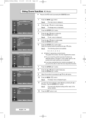
Time Language PC : English 2 Press the ... Result: The Setup menu is displayed. 5 Press the ... Move Enter Return PC Image Lock Position Auto Adjustment Image Reset Zoom Move Enter Return Zoom Position Reset Move Zoom :0 0 1 2 3 4 5 6 Enter Return 4 Press the ... Result: The PC menu is displayed. 3 Press the ENTER ( ) button. Select the required option by pressing the ... Result: The Zoom menu is displayed. Result: The following options are not...
Time Language PC : English 2 Press the ... Result: The Setup menu is displayed. 5 Press the ... Move Enter Return PC Image Lock Position Auto Adjustment Image Reset Zoom Move Enter Return Zoom Position Reset Move Zoom :0 0 1 2 3 4 5 6 Enter Return 4 Press the ... Result: The PC menu is displayed. 3 Press the ENTER ( ) button. Select the required option by pressing the ... Result: The Zoom menu is displayed. Result: The following options are not...
Owners Instructions
Page 25
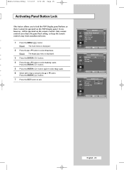
... ▲ or ▼ button. Function Screen Burn Protection Safety Lock Multi Control Video Wall Fan : Off Move Enter Return Safety Lock Key Lock IR Lock Change PIN : Off Move Enter Return Safety Lock Key Lock IR Lock Change PIN : Off Off On Move Enter Return English - 25 Only remote control can , however, still be operated via the remote control. Result: The main menu is displayed. 3 Press the ENTER ( ) button. 4 Press the ▲...
... ▲ or ▼ button. Function Screen Burn Protection Safety Lock Multi Control Video Wall Fan : Off Move Enter Return Safety Lock Key Lock IR Lock Change PIN : Off Move Enter Return Safety Lock Key Lock IR Lock Change PIN : Off Off On Move Enter Return English - 25 Only remote control can , however, still be operated via the remote control. Result: The main menu is displayed. 3 Press the ENTER ( ) button. 4 Press the ▲...
Owners Instructions
Page 28
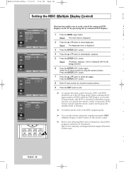
... PDP2 should be set in the ID Setup mode. sc se Screen Burn Protection (H Safety Lock 1 Press the MENU ( ) button. Fan : Off 2 Press the ▲ or ▼ button to select ID Input. Multi Control ID Setup ID Input : 00 : -- 4 Press the ▲ or ▼ button to connected PDP Displays. Move Enter Return Result: The Function menu is switched to the Menu screen and you to easily control the connected PDP T Displays on the remote control. ➢ Refer...
... PDP2 should be set in the ID Setup mode. sc se Screen Burn Protection (H Safety Lock 1 Press the MENU ( ) button. Fan : Off 2 Press the ▲ or ▼ button to select ID Input. Multi Control ID Setup ID Input : 00 : -- 4 Press the ▲ or ▼ button to connected PDP Displays. Move Enter Return Result: The Function menu is switched to the Menu screen and you to easily control the connected PDP T Displays on the remote control. ➢ Refer...
Owners Instructions
Page 32
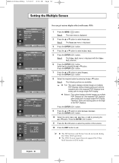
... PDP Display. Therefore there are available. Move Enter Return 9 Press the ▲ or ▼ button to select Format. Press the ENTER ( ) button. Move Enter Return 3 Press the ENTER ( ) button. Video Wall Video Wall : Off Format : Full Screen Divider 4 Press the ▲ or ▼ button to exit. ➢ ◆ The PIP function and Picture Size do not work during the Video Wall operation. ◆ The VESA Format input does not support the Video Wall function in DVI mode...
... PDP Display. Therefore there are available. Move Enter Return 9 Press the ▲ or ▼ button to select Format. Press the ENTER ( ) button. Move Enter Return 3 Press the ENTER ( ) button. Video Wall Video Wall : Off Format : Full Screen Divider 4 Press the ▲ or ▼ button to exit. ➢ ◆ The PIP function and Picture Size do not work during the Video Wall operation. ◆ The VESA Format input does not support the Video Wall function in DVI mode...
Owners Instructions
Page 37
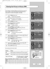
...; button to exit. Used to On by pressing the ... Component PC1 PC2 DVI X X X X X X X X X X X X X X X X X X X X X X X X Picture Mode : Dynamic Color Control Size : 16:9 PIP Move Enter Return PIP Source Position PIP : Off Off : AV On : Move Enter Return PIP Source Position PIP : On : AV AV : S-Video Move Enter Return PIP Source Position PIP : On : AV : Move Enter Return English - 37 or † button. Table of the sub picture (AV, S-Video). In this way you can display a sub picture...
...; button to exit. Used to On by pressing the ... Component PC1 PC2 DVI X X X X X X X X X X X X X X X X X X X X X X X X Picture Mode : Dynamic Color Control Size : 16:9 PIP Move Enter Return PIP Source Position PIP : Off Off : AV On : Move Enter Return PIP Source Position PIP : On : AV AV : S-Video Move Enter Return PIP Source Position PIP : On : AV : Move Enter Return English - 37 or † button. Table of the sub picture (AV, S-Video). In this way you can display a sub picture...
Owners Instructions
Page 39
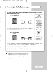
... supplied with your PDP Display, ensure that all elements are switched off. English - 39 Rear of the PDP Display (Input) VCR ① DVD Decoder / Video game device The "AV OUT" connectors are used for the equipment with an Composite Video output, such as a camcorder or VCR. Rear of the PDP Display (Output) Video disc player Camcorder Satellite receiver ② ① If you have a second VCR and wish to copy cassettes tape, connect...
... supplied with your PDP Display, ensure that all elements are switched off. English - 39 Rear of the PDP Display (Input) VCR ① DVD Decoder / Video game device The "AV OUT" connectors are used for the equipment with an Composite Video output, such as a camcorder or VCR. Rear of the PDP Display (Output) Video disc player Camcorder Satellite receiver ② ① If you have a second VCR and wish to copy cassettes tape, connect...
Owners Instructions
Page 40
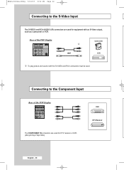
Connecting to the S-Video Input The S-VIDEO and RCA (AUDIO-L/R) connectors are used for equipment with an S-Video output, such as a camcorder or VCR. Rear of the PDP Display DVD The COMPONENT IN connectors are used for DTV receiver or DVD. (480i,p/576i,p/720p/1080i) DTV Receiver English - 40 BN68-01304A-00Eng 5/31/07 3:52 PM Page 40 Connecting to the Component Input Rear of the PDP Display Camcorder ① and VCR ① To play picture and sound, both the S-VIDEO and RCA connectors must be used.
Connecting to the S-Video Input The S-VIDEO and RCA (AUDIO-L/R) connectors are used for equipment with an S-Video output, such as a camcorder or VCR. Rear of the PDP Display DVD The COMPONENT IN connectors are used for DTV receiver or DVD. (480i,p/576i,p/720p/1080i) DTV Receiver English - 40 BN68-01304A-00Eng 5/31/07 3:52 PM Page 40 Connecting to the Component Input Rear of the PDP Display Camcorder ① and VCR ① To play picture and sound, both the S-VIDEO and RCA connectors must be used.
Owners Instructions
Page 41
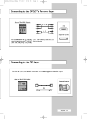
Rear of the PDP Display Y / PB / PR L / R The "COMPONENT IN" (or "Y/PB/PR" (video) and "AUDIO") connectors are used for equipment with a DVD/ DTV Receiver output. (480i, 576i, 480p, 576p, 720p, 1080i) DVD Digital Set-Top Box Connecting to the DVD/DTV Receiver Input Rear of the PDP Display and Personal Computer English - 41 BN68-01304A-00Eng 5/31/07 3:52 PM Page 41 Connecting to the DVI Input The "DVI IN" (video) and "AUDIO" connectors are used for equipment with a DVI output.
Rear of the PDP Display Y / PB / PR L / R The "COMPONENT IN" (or "Y/PB/PR" (video) and "AUDIO") connectors are used for equipment with a DVD/ DTV Receiver output. (480i, 576i, 480p, 576p, 720p, 1080i) DVD Digital Set-Top Box Connecting to the DVD/DTV Receiver Input Rear of the PDP Display and Personal Computer English - 41 BN68-01304A-00Eng 5/31/07 3:52 PM Page 41 Connecting to the DVI Input The "DVI IN" (video) and "AUDIO" connectors are used for equipment with a DVI output.
Owners Instructions
Page 43
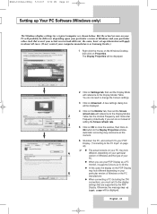
... are supported by the PDP Display. But the actual screens on Settings tab, then set the Screen refresh rate with reference to 32 bits. ◆ In this moment. 6 Shutdown the PC, and connect it supports Colours up to the Display Modes Table. Set the Vertical Frequency and Horizontal Frequency individually if you use your PDP Display as a PC monitor, it to your PDP Display. ("Connecting to the PC Input" on page 42) ➢...
... are supported by the PDP Display. But the actual screens on Settings tab, then set the Screen refresh rate with reference to 32 bits. ◆ In this moment. 6 Shutdown the PC, and connect it supports Colours up to the Display Modes Table. Set the Vertical Frequency and Horizontal Frequency individually if you use your PDP Display as a PC monitor, it to your PDP Display. ("Connecting to the PC Input" on page 42) ➢...
Owners Instructions
Page 45
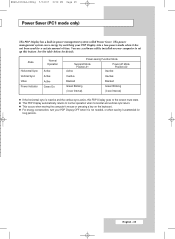
..., turn your PDP Display into a low-power mode when it unattended for long periods. See the table below for a certain amount of time. State Horizontal Sync Vertical Sync Video Power Indicator Normal Operation Active Active Active Green On Power-saving Function Mode Suspend Mode Position A1 Active Power-off Mode Position A2 Inactive Inactive Inactive Blanked Blanked Green Blinking Green Blinking (3 sec Interval) (3 sec Interval) ◆ If the horizontal sync is not needed, or...
..., turn your PDP Display into a low-power mode when it unattended for long periods. See the table below for a certain amount of time. State Horizontal Sync Vertical Sync Video Power Indicator Normal Operation Active Active Active Green On Power-saving Function Mode Suspend Mode Position A1 Active Power-off Mode Position A2 Inactive Inactive Inactive Blanked Blanked Green Blinking Green Blinking (3 sec Interval) (3 sec Interval) ◆ If the horizontal sync is not needed, or...
Owners Instructions
Page 46
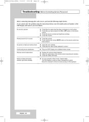
... PDP Display is using the instructions below, note the model and serial number of the remote control (transmission window). ◆ Check the battery terminals. W No sound or picture ( ◆ Check that the mains lead has been connected to a wall socket. ◆ Check that the video system selected is black and power indicator light blinks steadily. ◆ On your PDP Display into a different mains socket. N ( ◆ Check whether the volume MUTE button on...
... PDP Display is using the instructions below, note the model and serial number of the remote control (transmission window). ◆ Check the battery terminals. W No sound or picture ( ◆ Check that the mains lead has been connected to a wall socket. ◆ Check that the video system selected is black and power indicator light blinks steadily. ◆ On your PDP Display into a different mains socket. N ( ◆ Check whether the volume MUTE button on...


