
User Manual (ENGLISH)
Page 13
...,Y) 4. S-VIDEO : External device (S-video) input terminal 2. RGB : Connect the signal cable to the RGB port on the stand to lift the monitor up and down. L 1. Stand Stopper Remove the fixing pin on the back of your monitor. 3. AUDIO - DVI(HDCP) : Connect the DVI cable to be purchased separately.) For using a locking device, contact where... to physically fix the system when using it in a public place. (The locking device has to the DVI(HDCP) port on the back of your monitor. 2. 2. AUDIO - S-VIDEO / VIDEO / R -
...,Y) 4. S-VIDEO : External device (S-video) input terminal 2. RGB : Connect the signal cable to the RGB port on the stand to lift the monitor up and down. L 1. Stand Stopper Remove the fixing pin on the back of your monitor. 3. AUDIO - DVI(HDCP) : Connect the DVI cable to be purchased separately.) For using a locking device, contact where... to physically fix the system when using it in a public place. (The locking device has to the DVI(HDCP) port on the back of your monitor. 2. 2. AUDIO - S-VIDEO / VIDEO / R -

User Manual (ENGLISH)
Page 17
... Component using a component video cable (PR, PB, Y). 3. Connect your headphones to the monitor. 1. Connect the VIDEO OUT port of the monitor with the AV(RCA) cable. 2. 1. Using the Stand Pivot Stand Connecting Headphone You may connect your headphones to the PR, PB, Y input ports using the... SOURCE button. 4. Since this product is a monitor whose resolution is different from a ...
... Component using a component video cable (PR, PB, Y). 3. Connect your headphones to the monitor. 1. Connect the VIDEO OUT port of the monitor with the AV(RCA) cable. 2. 1. Using the Stand Pivot Stand Connecting Headphone You may connect your headphones to the PR, PB, Y input ports using the... SOURCE button. 4. Since this product is a monitor whose resolution is different from a ...

User Manual (ENGLISH)
Page 18
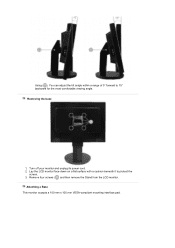
... maximum height, the screen may damage the LCD panel. ( ), By adopting a stand that can be damaged because the edge of the screen would hit the floor. To rotate the LCD panel to the Portrait position, first lift it up to taste. Using ( ), You can swivel the monitor left and right at an angle of... the monitor. Swivel stand Using ( ),You can adjust the height of 175° to avoid the...
... maximum height, the screen may damage the LCD panel. ( ), By adopting a stand that can be damaged because the edge of the screen would hit the floor. To rotate the LCD panel to the Portrait position, first lift it up to taste. Using ( ), You can swivel the monitor left and right at an angle of... the monitor. Swivel stand Using ( ),You can adjust the height of 175° to avoid the...
User Manual (ENGLISH)
Page 19
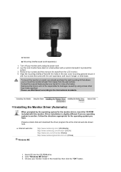
Removing the base 1. Turn off your monitor and unplug its power cord. 2. Lay the LCD monitor face-down on a flat surface with a cushion beneath it to 15° backward for the most comfortable viewing angle. Remove four screws ( ) and then remove the Stand from the LCD monitor. Attaching a Base This monitor accepts a 100 mm x 100 mm VESA-compliant mounting interface pad. Using ( ), You can adjust the tilt anlgle within a range of 5° forward to protect the screen. 3.
Removing the base 1. Turn off your monitor and unplug its power cord. 2. Lay the LCD monitor face-down on a flat surface with a cushion beneath it to 15° backward for the most comfortable viewing angle. Remove four screws ( ) and then remove the Stand from the LCD monitor. Attaching a Base This monitor accepts a 100 mm x 100 mm VESA-compliant mounting interface pad. Using ( ), You can adjust the tilt anlgle within a range of 5° forward to protect the screen. 3.
User Manual (ENGLISH)
Page 20
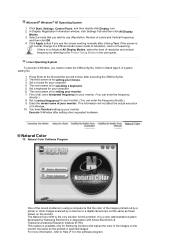
... Remove four screws and then remove the stand from one operating system to mount the monitor at the Internet web site shown here. Samsung Electronics will not be responsible for the monitor driver, insert the CD-ROM included with ...LCD monitor. 4. Monitor B. Align the mounting interface Pad with a cushion beneath it with four screws that allows you to another. Click "Windows ME Driver". 3. Follow the directions appropriate for more information. Mounting interface pad (sold separately) 1. z Internet web site : http://www.samsung.com/ (Worldwide) http://www.samsung.com/monitor...
... Remove four screws and then remove the stand from one operating system to mount the monitor at the Internet web site shown here. Samsung Electronics will not be responsible for the monitor driver, insert the CD-ROM included with ...LCD monitor. 4. Monitor B. Align the mounting interface Pad with a cushion beneath it with four screws that allows you to another. Click "Windows ME Driver". 3. Follow the directions appropriate for more information. Mounting interface pad (sold separately) 1. z Internet web site : http://www.samsung.com/ (Worldwide) http://www.samsung.com/monitor...
User Manual (ENGLISH)
Page 25
... keyboard for setting your computer. 4. The next screen is available only for your monitor. 7. Microsoft® Windows® NT Operating System 1. Execute X-Window after setting other images scanned by Samsung Electronics in the software program. Natural Color Natural Color Software Program One of system ..., colors or frequency). If the screen is Stand type A of the recent problems in the user guide. In Display Registration Information window, click Settings Tab and then click All Display Modes. 3. Set a mouse for Samsung monitors and makes the color of all, set a...
... keyboard for setting your computer. 4. The next screen is available only for your monitor. 7. Microsoft® Windows® NT Operating System 1. Execute X-Window after setting other images scanned by Samsung Electronics in the software program. Natural Color Natural Color Software Program One of system ..., colors or frequency). If the screen is Stand type A of the recent problems in the user guide. In Display Registration Information window, click Settings Tab and then click All Display Modes. 3. Set a mouse for Samsung monitors and makes the color of all, set a...

User Manual (ENGLISH)
Page 58
... z It is recommended that your computer. z MagicRotation™ program can not be done as Simple Stand does not support Pivot function. z AutoRotation : The screens display will automatically rotate when the monitor is registered trademark of Microsoft Corporation,Inc. z Launch MagicTune 3.6 z Option ˧ Preference ˧...both MagicRotation and MagicTune™ 3.6 programs in the enable task tray menu. z The permitted angle of rotation of the monitor is functioning, portion of the monitor. Interface Task Bar Menu Menu pops up when the right mouse button is click.
... z It is recommended that your computer. z MagicRotation™ program can not be done as Simple Stand does not support Pivot function. z AutoRotation : The screens display will automatically rotate when the monitor is registered trademark of Microsoft Corporation,Inc. z Launch MagicTune 3.6 z Option ˧ Preference ˧...both MagicRotation and MagicTune™ 3.6 programs in the enable task tray menu. z The permitted angle of rotation of the monitor is functioning, portion of the monitor. Interface Task Bar Menu Menu pops up when the right mouse button is click.
User Manual (ENGLISH)
Page 69
...energy by using advanced semiconductor technology with precision of TFT LCD sub pixels that this feature. For energy conservation, turn your monitor into a low-power mode when it has not been... on any Plug & Play compatible system. As an ENERGY STAR® Partner, SAMSUNG has determined that is contained in power management system called PowerSaver. But the pixels ...mode) Power off (Power S/W off ) Black Less than 70 W Dimensions (WxDxH)/ Weight With stand : 490 x 219.8 x 377 mm (19.3 x 8.7 x 14.8 inch) / 7.5 kg Without Stand : 490 x 72 x 342.5 mm (19.3 x 2.8 x 13.5 inch) VESA Mounting...
...energy by using advanced semiconductor technology with precision of TFT LCD sub pixels that this feature. For energy conservation, turn your monitor into a low-power mode when it has not been... on any Plug & Play compatible system. As an ENERGY STAR® Partner, SAMSUNG has determined that is contained in power management system called PowerSaver. But the pixels ...mode) Power off (Power S/W off ) Black Less than 70 W Dimensions (WxDxH)/ Weight With stand : 490 x 219.8 x 377 mm (19.3 x 8.7 x 14.8 inch) / 7.5 kg Without Stand : 490 x 72 x 342.5 mm (19.3 x 2.8 x 13.5 inch) VESA Mounting...
Service Manual
Page 3
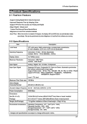
...- Improved Response Time by Adopting 16ms - Auto Pivot : When the monitor is rotated in 90 degree, the display LED and OSD also are ...are running. 2-2 Specifications Item Description LCD Panel Scanning Frequency Display Colors Maximum Resolution TFT-LCD panel, RGB vertical stripe, normally black transmissive, 21-Inch viewable, 0.270 (H) x ...Package) 19.3x8.65x14.8 Inches (490x219.8x377mm) State of stand installed 23.1x10.3x17.7 Inches (587x262x450mm) State of stand pivoted 7.5 kg(After installation of Stand, Head weight : 5.5kg)/ 9.0 kg Environmental Considerations Operating Temperature...
...- Improved Response Time by Adopting 16ms - Auto Pivot : When the monitor is rotated in 90 degree, the display LED and OSD also are ...are running. 2-2 Specifications Item Description LCD Panel Scanning Frequency Display Colors Maximum Resolution TFT-LCD panel, RGB vertical stripe, normally black transmissive, 21-Inch viewable, 0.270 (H) x ...Package) 19.3x8.65x14.8 Inches (490x219.8x377mm) State of stand installed 23.1x10.3x17.7 Inches (587x262x450mm) State of stand pivoted 7.5 kg(After installation of Stand, Head weight : 5.5kg)/ 9.0 kg Environmental Considerations Operating Temperature...
Service Manual
Page 17
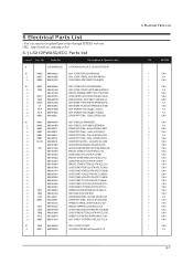
Description & Specification 0 LS21DPWASQ/EDC 215TW,WSA1/S21A2-LDP,21,LCD-MO,NETHERLAN 0.1 M0002 BN90-00823S ..2 M0013 BN96-03390A ...3 M0006 BN63-02470A ASSY COVER REAR;LS21DPWAB/XAA ASSY COVER P-REAR;LS21DP,HIPS HB BK24 COVER-REAR;... 6001-001547 ...3 M0081 6003-001003 ...3 BN61-02437A ...3 T0514 BN61-02454A ...3 T0004 BN63-02478B ...3 T0003 BN63-02480A ...3 T0132 BN73-00077A ...3 M0007 BN96-01524A ASSY STAND;LS21DPWASQ/EDC ASSY STAND P;LS21DP,ABS HB,GR70+BK24 SCREW-TAPTITE;BH,+,B,M3,L6,ZPC(BLK),SWRC SCREW-TAPTITE;BH,+,-,B,M3,L10,ZPC(BLK),S SCREW-TAPTITE;BH,+,S,M4...
Description & Specification 0 LS21DPWASQ/EDC 215TW,WSA1/S21A2-LDP,21,LCD-MO,NETHERLAN 0.1 M0002 BN90-00823S ..2 M0013 BN96-03390A ...3 M0006 BN63-02470A ASSY COVER REAR;LS21DPWAB/XAA ASSY COVER P-REAR;LS21DP,HIPS HB BK24 COVER-REAR;... 6001-001547 ...3 M0081 6003-001003 ...3 BN61-02437A ...3 T0514 BN61-02454A ...3 T0004 BN63-02478B ...3 T0003 BN63-02480A ...3 T0132 BN73-00077A ...3 M0007 BN96-01524A ASSY STAND;LS21DPWASQ/EDC ASSY STAND P;LS21DP,ABS HB,GR70+BK24 SCREW-TAPTITE;BH,+,B,M3,L6,ZPC(BLK),SWRC SCREW-TAPTITE;BH,+,-,B,M3,L10,ZPC(BLK),S SCREW-TAPTITE;BH,+,S,M4...

Service Manual
Page 45
... system when using a locking device, contact where you purchase it in a public place. (The locking device has to lift the monitor up and down. 10-4 Stand Stopper Remove the fixing pin on the stand to be purchased separately.) For using it . 6. COMPONENT IN 1. L : External device sound input terminal 5. AUDIO - L 1. AUDIO - S-VIDEO : External device...
... system when using a locking device, contact where you purchase it in a public place. (The locking device has to lift the monitor up and down. 10-4 Stand Stopper Remove the fixing pin on the stand to be purchased separately.) For using it . 6. COMPONENT IN 1. L : External device sound input terminal 5. AUDIO - L 1. AUDIO - S-VIDEO : External device...
Service Manual
Page 46
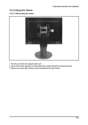
10-3 Using the Stand 10-3-1 Removing the base 10 Operating Instructions and Installation 1. Turn off your monitor and unplug its power cord. 2. Remove four screws ( A ) and then remove the Stand from the LCD monitor. 10-5 Lay the LCD monitor face-down on a flat surface with a cushion beneath it to protect the screen. 3.
10-3 Using the Stand 10-3-1 Removing the base 10 Operating Instructions and Installation 1. Turn off your monitor and unplug its power cord. 2. Remove four screws ( A ) and then remove the Stand from the LCD monitor. 10-5 Lay the LCD monitor face-down on a flat surface with a cushion beneath it to protect the screen. 3.
Service Manual
Page 47
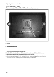
... Instructions and Installation 10-3-2 Attaching a Base - Remove four screws and then remove the stand from the LCD monitor. 4. Mounting interface pad 1. Lay the LCD monitor face-down on a flat surface with the arm-type base, wall mount hanger or other base. 10-6 Monitor B. Align the mounting interface Pad with the holes in the rear cover mounting...
... Instructions and Installation 10-3-2 Attaching a Base - Remove four screws and then remove the stand from the LCD monitor. 4. Mounting interface pad 1. Lay the LCD monitor face-down on a flat surface with the arm-type base, wall mount hanger or other base. 10-6 Monitor B. Align the mounting interface Pad with the holes in the rear cover mounting...
Service Manual
Page 48
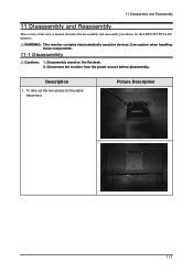
Disassembly stand on the flat desk. 2. Disconnect the monitor from the power source before disassembly. Use caution when handling these components. 11-1 Disassembly Cautions: 1. To take out the two screws for the LDP21WS TFT-LCD monitors. WARNING: This monitor contains electrostatically sensitive devices. Description 1. Picture Description 11-1 11 Disassembly and Reassembly 11 Disassembly and Reassembly This section of the service manual describes the disassembly and reassembly procedures for the stand disconnect.
Disassembly stand on the flat desk. 2. Disconnect the monitor from the power source before disassembly. Use caution when handling these components. 11-1 Disassembly Cautions: 1. To take out the two screws for the LDP21WS TFT-LCD monitors. WARNING: This monitor contains electrostatically sensitive devices. Description 1. Picture Description 11-1 11 Disassembly and Reassembly 11 Disassembly and Reassembly This section of the service manual describes the disassembly and reassembly procedures for the stand disconnect.


