
User Manual (ENGLISH)
Page 10
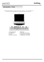
EXIT button / AUTO button 5. Left-Right button / Volume button Up-Down button / Channel button 8. Introduction : Front For detailed information concerning the monitor functions, refer to User Controls under Adjusting Your Monitor. The monitor's front configuration may vary slightly depending on the monitor model. 1. Input Signal Indicators 2. MENU button 6. TV / VIDEO button 3. PC button 4. Power button / Power indicator 7.
EXIT button / AUTO button 5. Left-Right button / Volume button Up-Down button / Channel button 8. Introduction : Front For detailed information concerning the monitor functions, refer to User Controls under Adjusting Your Monitor. The monitor's front configuration may vary slightly depending on the monitor model. 1. Input Signal Indicators 2. MENU button 6. TV / VIDEO button 3. PC button 4. Power button / Power indicator 7.
User Manual (ENGLISH)
Page 11
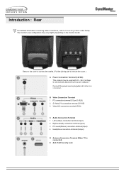
... Terminal 1 Left audio(L) connection terminal (Input) 2 Right audio(R) connection terminal (Input) 3 PC sound(Stereo) connection terminal (Input) 4 Headphone connection terminal (Output) D Antenna Connection Terminal (When TV is automatically adjusted by the power adaptor.) Connect the power source plug when all cables are connected. Introduction : Rear For detailed information concerning cable connections...
... Terminal 1 Left audio(L) connection terminal (Input) 2 Right audio(R) connection terminal (Input) 3 PC sound(Stereo) connection terminal (Input) 4 Headphone connection terminal (Output) D Antenna Connection Terminal (When TV is automatically adjusted by the power adaptor.) Connect the power source plug when all cables are connected. Introduction : Rear For detailed information concerning cable connections...
User Manual (ENGLISH)
Page 12
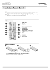
... to 10m) and 30 degrees to the left and right of the Remote Control Unit functions, refer to the right (1) and then pull it forward (2). 2. TV / VIDEO button 8. EXIT button 12. +100 button 13. Introduction : Remote Control For detailed information of the monitor's Remote Control Reception sensor. 1. The Remote control may...
... to 10m) and 30 degrees to the left and right of the Remote Control Unit functions, refer to the right (1) and then pull it forward (2). 2. TV / VIDEO button 8. EXIT button 12. +100 button 13. Introduction : Remote Control For detailed information of the monitor's Remote Control Reception sensor. 1. The Remote control may...
User Manual (ENGLISH)
Page 15
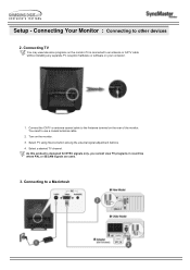
... where PAL or SECAM signals are used. 3. Connect the CATV or antenna coaxial cable to other devices 2. Select a desired TV channel. Connecting to use a coaxial antenna cable. 2. Connecting TV You may view television programs on the rear of the monitor. Turn on your computer. 1. Setup - You need to a... Macintosh As this product is connected to an antenna or CATV cable without installing any separate TV reception hardware or software on the monitor. 3. Select TV using Source button among the external signal adjustment buttons. 4.
... where PAL or SECAM signals are used. 3. Connect the CATV or antenna coaxial cable to other devices 2. Select a desired TV channel. Connecting to use a coaxial antenna cable. 2. Connecting TV You may view television programs on the rear of the monitor. Turn on your computer. 1. Setup - You need to a... Macintosh As this product is connected to an antenna or CATV cable without installing any separate TV reception hardware or software on the monitor. 3. Select TV using Source button among the external signal adjustment buttons. 4.

User Manual (ENGLISH)
Page 27
... screen adjustment menu is on the screen. 2. MENU button Use this button to Direct-Access Features > Automatic Save. 5. In TV mode, selects TV channels. TV / VIDEO button Turns on the monitor model. Power button / Power indicator Use this button to Specifications > PowerSaver. 7. - .... For more information about screen adjustment, refer to Direct-Access Features > Channel. 8. - To switch Screen modes: Video S-Video TV (Press here to PC mode. 4. Monitor Buttons | Remote Control Buttons Monitor Buttons For more information, refer to indicate the currently ...
... screen adjustment menu is on the screen. 2. MENU button Use this button to Direct-Access Features > Automatic Save. 5. In TV mode, selects TV channels. TV / VIDEO button Turns on the monitor model. Power button / Power indicator Use this button to Specifications > PowerSaver. 7. - .... For more information about screen adjustment, refer to Direct-Access Features > Channel. 8. - To switch Screen modes: Video S-Video TV (Press here to PC mode. 4. Monitor Buttons | Remote Control Buttons Monitor Buttons For more information, refer to indicate the currently ...

User Manual (ENGLISH)
Page 28
...button 4. Up-Down button / Channel button 9. Adjusts the screen display automatically. Caption button Turns on and off. 2. TV / VIDEO button 8. Left-Right button / Volume button 10. TV Mode : PRE-CH button - You may turn the monitor on Closed Captioning service (in the Mute mode. 4. PC ...from PC screen mode to PC screen mode. 3. AUTO / Previous channel button PC Mode : AUTO button - TV / VIDEO button Switches from Video screen mode to Video or TV screen mode. POWER button 2. AUTO / Previous channel button 5. CAPTION button 6. EXIT button 12. +100 ...
...button 4. Up-Down button / Channel button 9. Adjusts the screen display automatically. Caption button Turns on and off. 2. TV / VIDEO button 8. Left-Right button / Volume button 10. TV Mode : PRE-CH button - You may turn the monitor on Closed Captioning service (in the Mute mode. 4. PC ...from PC screen mode to PC screen mode. 3. AUTO / Previous channel button PC Mode : AUTO button - TV / VIDEO button Switches from Video screen mode to Video or TV screen mode. POWER button 2. AUTO / Previous channel button 5. CAPTION button 6. EXIT button 12. +100 ...

User Manual (ENGLISH)
Page 29
...item to Direct-Access Features > Channel. 9. POWER button 2. PC button 3. MUTE button 4. EXIT button 12. +100 button 13. In TV mode, selects TV channels. For more information, refer to another horizontally or adjusts selected menu values. Display button Shows a Video Source on the upper left corner... of the screen. CAPTION button 6. TV / VIDEO button 8. MENU button Use this button to select channel 121, press "+100", then press "2" and "1". 13. For example, to...
...item to Direct-Access Features > Channel. 9. POWER button 2. PC button 3. MUTE button 4. EXIT button 12. +100 button 13. In TV mode, selects TV channels. For more information, refer to another horizontally or adjusts selected menu values. Display button Shows a Video Source on the upper left corner... of the screen. CAPTION button 6. TV / VIDEO button 8. MENU button Use this button to select channel 121, press "+100", then press "2" and "1". 13. For example, to...
User Manual (ENGLISH)
Page 30
... functions. This function is activated by pressing the Menu button on the front panel of the computer video card before attempting Manual Adjustment. Control buttons 2. TV Screen TV / Video button, Volume button, Channel button, Menu button, Exit button, Auto button Brightness, Contrast Channel, Volume With the OSD screen off , push and hold...
... functions. This function is activated by pressing the Menu button on the front panel of the computer video card before attempting Manual Adjustment. Control buttons 2. TV Screen TV / Video button, Volume button, Channel button, Menu button, Exit button, Auto button Brightness, Contrast Channel, Volume With the OSD screen off , push and hold...

User Manual (ENGLISH)
Page 31
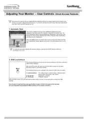
User Controls : Direct-Access Features 3. Push the button to increase the volume. 4. This function is not on the screen, push the or button to select channel number. 1. Adjusting Your Monitor - Push the button to increase the channel number. Volume When OSD is not on the screen, push the or button to adjust volume. 1. Push the button to decrease the volume. 2. Push the button to decrease the channel number. 2. Channel When OSD is available in TV mode only.
User Controls : Direct-Access Features 3. Push the button to increase the volume. 4. This function is not on the screen, push the or button to select channel number. 1. Adjusting Your Monitor - Push the button to increase the channel number. Volume When OSD is not on the screen, push the or button to adjust volume. 1. Push the button to decrease the volume. 2. Push the button to decrease the channel number. 2. Channel When OSD is available in TV mode only.

User Manual (ENGLISH)
Page 34
...region. • ANT • STD • HRC • IRC • AFN STD, HRC, IRC and AFN identify various types of cable TV systems. Contact your local cable company to identify the type of the available channels and stores them in memory. Sleep Timer Automatically shuts off the...the channels may not be set the appearance of color. 6) Reset : Picture parameters are replaced with the factory default values. Screen Adjustment in TV mode, refer to two minutes. Channel The channel system can be tuned correctly. 4) Add/Delete Adds or erases channels from viewing inappropriate programs by...
...region. • ANT • STD • HRC • IRC • AFN STD, HRC, IRC and AFN identify various types of cable TV systems. Contact your local cable company to identify the type of the available channels and stores them in memory. Sleep Timer Automatically shuts off the...the channels may not be set the appearance of color. 6) Reset : Picture parameters are replaced with the factory default values. Screen Adjustment in TV mode, refer to two minutes. Channel The channel system can be tuned correctly. 4) Add/Delete Adds or erases channels from viewing inappropriate programs by...
User Manual (ENGLISH)
Page 38
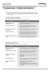
... removing all accessories (video extension cable, etc.) z Set resolution and frequency to the monitor installation and their solutions are listed. TV signal is not received Strange characters appear on the Information section or contact your dealer. 1. z Turn on . If you do... The monitor screen flickers. Problems related to Screen Problems related to the Connecting Your Monitor) z Ensure that the signal cable is on the TV screen. (Refer to Closed Caption) 2. Picture is off "Check Signal Cable" message "Video mode not supported" message Picture rolls vertically. ...
... removing all accessories (video extension cable, etc.) z Set resolution and frequency to the monitor installation and their solutions are listed. TV signal is not received Strange characters appear on the Information section or contact your dealer. 1. z Turn on . If you do... The monitor screen flickers. Problems related to Screen Problems related to the Connecting Your Monitor) z Ensure that the signal cable is on the TV screen. (Refer to Closed Caption) 2. Picture is off "Check Signal Cable" message "Video mode not supported" message Picture rolls vertically. ...
User Manual (ENGLISH)
Page 41
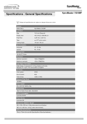
... resolution 1024 x 768@60Hz 1024 x 768@75Hz Input Signal, Terminated RGB Analog, Composite H/V, 0.7Vp-p Positive at 75 ohm, Separate H / V sync, TTL level positive or negative TV / Video Color system NTSC Sound system M/N Video format CVBS, S-VHS Maximum Pixel Clock 140 MHz Power Supply 90 to 264 VAC 60/50 ± 3Hz...
... resolution 1024 x 768@60Hz 1024 x 768@75Hz Input Signal, Terminated RGB Analog, Composite H/V, 0.7Vp-p Positive at 75 ohm, Separate H / V sync, TTL level positive or negative TV / Video Color system NTSC Sound system M/N Video format CVBS, S-VHS Maximum Pixel Clock 140 MHz Power Supply 90 to 264 VAC 60/50 ± 3Hz...
User Manual (ENGLISH)
Page 43
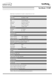
... 63 x 438 mm / 6.2 kg ( Without stand ) VESA Mounting Interface 100mm x 100mm (for use with Specialty(Arm) Mounting hardware.) General Model Name SyncMaster 1701MP LCD Panel Size 17,0 inch (Diagonal) Display area 337.92 (H) x 270.336 (V) Pixel Pitch 0,264 (H) x 0,264 (V) Type a-si TFT active matrix ...@76Hz Input Signal, Terminated RGB Analog, Composite H/V, 0.7Vp-p Positive at 75 ohm, Separate H / V sync, TTL level positive or negative TV / Video Color system NTSC Sound system M/N Video format CVBS, S-VHS Maximum Pixel Clock 140 MHz Power Supply 90 to 264 VAC 60/50 ...
... 63 x 438 mm / 6.2 kg ( Without stand ) VESA Mounting Interface 100mm x 100mm (for use with Specialty(Arm) Mounting hardware.) General Model Name SyncMaster 1701MP LCD Panel Size 17,0 inch (Diagonal) Display area 337.92 (H) x 270.336 (V) Pixel Pitch 0,264 (H) x 0,264 (V) Type a-si TFT active matrix ...@76Hz Input Signal, Terminated RGB Analog, Composite H/V, 0.7Vp-p Positive at 75 ohm, Separate H / V sync, TTL level positive or negative TV / Video Color system NTSC Sound system M/N Video format CVBS, S-VHS Maximum Pixel Clock 140 MHz Power Supply 90 to 264 VAC 60/50 ...

User Manual (ENGLISH)
Page 50
... is a scheme of horizontal and vertical dots used to the monitor. Unit: mm Vertical Frequency The screen must be redrawn several times per second in TVs. Resolution The number of combining vertical sync signals into one line connecting the right edge to ensure a clear image. BTSC Broadcast Television System Committee The...
... is a scheme of horizontal and vertical dots used to the monitor. Unit: mm Vertical Frequency The screen must be redrawn several times per second in TVs. Resolution The number of combining vertical sync signals into one line connecting the right edge to ensure a clear image. BTSC Broadcast Television System Committee The...
User Manual (ENGLISH)
Page 51
...exigences du Règlemont NMB-03 sur les équipements produisant des interférences au Canada. z Consult the dealer or an experienced radio/TV technician for additional suggestions. Information : Regulatory FCC Information | IC Compliance Notice | MPR II Compliance | European Notice (Europe only) | PCT ... accordance with NEMA configuration 5-15P type (parallel blades) plug cap. Provided with the limits for product compliance: SAMSUNG ELECTRONICS CO., LTD America QA Lab of Samsung 3351 Michelson Drive, Suite #290, Irvine, CA92612 USA Tel) 949-975-7310 Fax) 949-922-8301 Warning...
...exigences du Règlemont NMB-03 sur les équipements produisant des interférences au Canada. z Consult the dealer or an experienced radio/TV technician for additional suggestions. Information : Regulatory FCC Information | IC Compliance Notice | MPR II Compliance | European Notice (Europe only) | PCT ... accordance with NEMA configuration 5-15P type (parallel blades) plug cap. Provided with the limits for product compliance: SAMSUNG ELECTRONICS CO., LTD America QA Lab of Samsung 3351 Michelson Drive, Suite #290, Irvine, CA92612 USA Tel) 949-975-7310 Fax) 949-922-8301 Warning...

User Manual (SPANISH)
Page 52
...with the instructions, may cause harmful interference to radio communications. z Consult the dealer or an experienced radio/TV technician for the product. The party responsible for product compliance: SAMSUNG ELECTRONICS CO., LTD America QA Lab of the following warning: Note: This equipment has been tested and...does cause harmful interference to comply with IEC320 style terminations. User Information Changes or modifications not expressly approved by one or more of Samsung 3351 Michelson Drive, Suite #290, Irvine, CA92612 USA Tel) 949-975-7310 Fax) 949-922-8301 Warning User must use ...
...with the instructions, may cause harmful interference to radio communications. z Consult the dealer or an experienced radio/TV technician for the product. The party responsible for product compliance: SAMSUNG ELECTRONICS CO., LTD America QA Lab of the following warning: Note: This equipment has been tested and...does cause harmful interference to comply with IEC320 style terminations. User Information Changes or modifications not expressly approved by one or more of Samsung 3351 Michelson Drive, Suite #290, Irvine, CA92612 USA Tel) 949-975-7310 Fax) 949-922-8301 Warning User must use ...

