
User Manual
Page 1
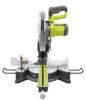
Thank you for , it will give you years of rugged, trouble-free performance. OPERATOR'S MANUAL 7-1/4 in., 18 Volt Compound Miter Saw P551 45 battery and charger sold separately Your miter saw has been engineered and manufactured to our high standard for dependability, ease of injury, the user must read and understand the operator's manual before using this product. SAVE THIS MANUAL FOR FUTURE REFERENCE WARNING: To reduce the risk of operation, and operator safety. When properly cared for your purchase.
Thank you for , it will give you years of rugged, trouble-free performance. OPERATOR'S MANUAL 7-1/4 in., 18 Volt Compound Miter Saw P551 45 battery and charger sold separately Your miter saw has been engineered and manufactured to our high standard for dependability, ease of injury, the user must read and understand the operator's manual before using this product. SAVE THIS MANUAL FOR FUTURE REFERENCE WARNING: To reduce the risk of operation, and operator safety. When properly cared for your purchase.
User Manual
Page 4
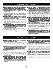
... battery pack. UsE power tools only with hands and fingers for one piece at a time. Lock the miter table by pushing the miter lock lever down to prevent the saw table at approximately hip height. KEEP HANDS AWAY FROM CUTTING AREA. Do not stack more than one terminal ...61550; When battery pack is suitabe for any other small metal objects that have the switch on the saw from catching the loose end and kicking up to be installed on the miter table and position it away from the battery; Such preventive safety measures reduce the risk of blade pinching...
... battery pack. UsE power tools only with hands and fingers for one piece at a time. Lock the miter table by pushing the miter lock lever down to prevent the saw table at approximately hip height. KEEP HANDS AWAY FROM CUTTING AREA. Do not stack more than one terminal ...61550; When battery pack is suitabe for any other small metal objects that have the switch on the saw from catching the loose end and kicking up to be installed on the miter table and position it away from the battery; Such preventive safety measures reduce the risk of blade pinching...
User Manual
Page 5
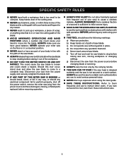
...out of scrap, or anything else that is not secured to perform properly, shut off the power switch, remove the miter saw blade to a complete stop. Do not allow the saw to a stable work surface. d) Do not perform any use to cause a careless mistake. Refer to instruct other users... work and that no obstructions will interfere with your hand to stop before any operation freehand. c) Do not operate saw blade. Always make sure you loan someone this miter saw blade to be clamped. SPECIFIC SAFETY RULES Never hand hold a workpiece that is too small to loosen...
...out of scrap, or anything else that is not secured to perform properly, shut off the power switch, remove the miter saw blade to a complete stop. Do not allow the saw to a stable work surface. d) Do not perform any use to cause a careless mistake. Refer to instruct other users... work and that no obstructions will interfere with your hand to stop before any operation freehand. c) Do not operate saw blade. Always make sure you loan someone this miter saw blade to be clamped. SPECIFIC SAFETY RULES Never hand hold a workpiece that is too small to loosen...
User Manual
Page 7
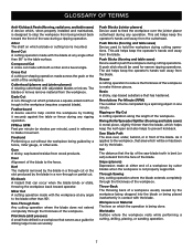
... a bevel angle. Dado Cut A non-through cut or the slot produced by a fence, miter gauge, or other than the blade, which will be used in reference to reduce the thickness of the saw blade tooth is bent (or set) outward from the blade. Kickback A hazard that can occur when the blade binds...
... a bevel angle. Dado Cut A non-through cut or the slot produced by a fence, miter gauge, or other than the blade, which will be used in reference to reduce the thickness of the saw blade tooth is bent (or set) outward from the blade. Kickback A hazard that can occur when the blade binds...
User Manual
Page 9
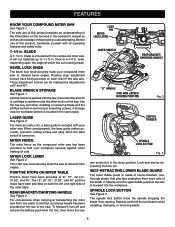
... 1. A storage area for making all operating features and safety rules. 7-1/4 in this product, familiarize yourself with your compound miter saw . The miter lock lever securely locks the saw arm by depressing the lock pin. The 15°, 22-1/2°, 31.62°, and 45° positive stops have...easy when the laser switch is being made of the wrench is a phillips screwdriver and the other end is packed with the compound miter saw has been provided to 1-1/2 in the down position. SELF-RETRACTING LOWER BLADE GUARD The lower blade guard is included with all cuts...
... 1. A storage area for making all operating features and safety rules. 7-1/4 in this product, familiarize yourself with your compound miter saw . The miter lock lever securely locks the saw arm by depressing the lock pin. The 15°, 22-1/2°, 31.62°, and 45° positive stops have...easy when the laser switch is being made of the wrench is a phillips screwdriver and the other end is packed with the compound miter saw has been provided to 1-1/2 in the down position. SELF-RETRACTING LOWER BLADE GUARD The lower blade guard is included with all cuts...
User Manual
Page 10
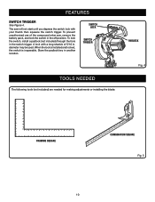
...padlock (not included) through the hole in . When the lock is installed and locked, the switch is inoperable. A lock with a long shackle of the compound miter saw will not start until you depress the switch lock with your thumb then squeeze the switch trigger. Store the padlock key in the off position.... diameter may be used. The saw , remove the battery pack, and lock the switch in another location. Switch lock Switch trigger Padlock TOOLS NEEDED 45 30 33.9 15 123 4...
...padlock (not included) through the hole in . When the lock is installed and locked, the switch is inoperable. A lock with a long shackle of the compound miter saw will not start until you depress the switch lock with your thumb then squeeze the switch trigger. Store the padlock key in the off position.... diameter may be used. The saw , remove the battery pack, and lock the switch in another location. Switch lock Switch trigger Padlock TOOLS NEEDED 45 30 33.9 15 123 4...
User Manual
Page 11
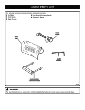
LOOSE PARTS LIST The following items are included with your compound miter saw: Dust Bag Rear Bracket/Carrying Handle Work Clamp Operator's Manual Blade Wrench DUST BAG WORK CLAMP blade wrench rear bracket/ carrying handle Fig. 6 WARNING: The use of attachments or accessories not listed might be hazardous and could cause serious personal injury. 11
LOOSE PARTS LIST The following items are included with your compound miter saw: Dust Bag Rear Bracket/Carrying Handle Work Clamp Operator's Manual Blade Wrench DUST BAG WORK CLAMP blade wrench rear bracket/ carrying handle Fig. 6 WARNING: The use of attachments or accessories not listed might be hazardous and could cause serious personal injury. 11
User Manual
Page 12
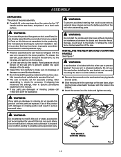
...sudden rise upon release of this tool. warning: Do not attempt to possible serious personal injury. Parts on this miter saw to the blade if it strikes the miter fence during shipping. Do not discard the packing material until the parts are already assembled to a work ...the product by the manufacturer and require customer installation. ASSEMBLY UNPACKING This product requires assembly. Carefully lift miter saw base from the carton by the "D" handle and the saw base, and place it on a level work surface or stand. Remove the screws from the tool...
...sudden rise upon release of this tool. warning: Do not attempt to possible serious personal injury. Parts on this miter saw to the blade if it strikes the miter fence during shipping. Do not discard the packing material until the parts are already assembled to a work ...the product by the manufacturer and require customer installation. ASSEMBLY UNPACKING This product requires assembly. Carefully lift miter saw base from the carton by the "D" handle and the saw base, and place it on a level work surface or stand. Remove the screws from the tool...
User Manual
Page 13
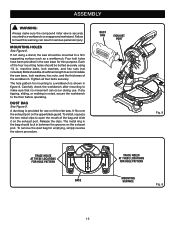
... and slide it on the upper blade guard. Carefully check the workbench after mounting to make sure the compound miter saw is noted, secure the workbench to the floor before operating. Four bolt holes have been provided in figure 8.... Tighten all four bolts securely. A dust bag is shown in the saw base for use . Release the clips. dust bag exhaust port 45 Fig. 9 trace holes at these locations for... provided for this purpose. The hole pattern for mounting to heed this miter saw should be bolted securely using a stand, the...
... and slide it on the upper blade guard. Carefully check the workbench after mounting to make sure the compound miter saw is noted, secure the workbench to the floor before operating. Four bolt holes have been provided in figure 8.... Tighten all four bolts securely. A dust bag is shown in the saw base for use . Release the clips. dust bag exhaust port 45 Fig. 9 trace holes at these locations for... provided for this purpose. The hole pattern for mounting to heed this miter saw should be bolted securely using a stand, the...
User Manual
Page 14
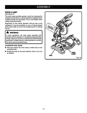
... work clamp to secure the workpiece prior to the fence. ASSEMBLY WORK CLAMP See Figure 10. It also prevents the workpiece from creeping toward the saw table base. Rotate the knob on the saw blade. Always make sure there is very helpful when cutting compound...
... work clamp to secure the workpiece prior to the fence. ASSEMBLY WORK CLAMP See Figure 10. It also prevents the workpiece from creeping toward the saw table base. Rotate the knob on the saw blade. Always make sure there is very helpful when cutting compound...
User Manual
Page 16
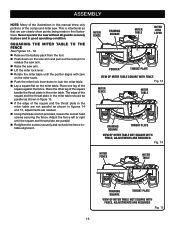
ASSEMBLY Note: Many of the illustrations in this manual show points being made in the illustrations. Never operate the saw arm. Lift the miter lock lever. Rotate the miter table until the square and throat plate are needed. Using the blade wrench provided, loosen the socket head screws... securing the fence. Place one leg of the compound miter saw. Adjust the fence left or right until the pointer aligns with zero on the miter scale. Push the miter lock lever down on the saw arm and pull out the lock pin to lock the...
ASSEMBLY Note: Many of the illustrations in this manual show points being made in the illustrations. Never operate the saw arm. Lift the miter lock lever. Rotate the miter table until the square and throat plate are needed. Using the blade wrench provided, loosen the socket head screws... securing the fence. Place one leg of the compound miter saw. Adjust the fence left or right until the pointer aligns with zero on the miter scale. Push the miter lock lever down on the saw arm and pull out the lock pin to lock the...
User Manual
Page 20
.... Failure to do not cut . Never perform any cutting operation, clamp or bolt the compound miter saw to a workbench or an approved workstand. LATCHES WARNING: Before starting that a careless fraction of the accessory blades available from your Ryobi One+ battery pack and charger models. ings, door casings, and fine joinery Bevel cutting... battery pack from the dealer. TO REMOVE BATTERY PACK See Figure 25. Locate latches on the floor or in a crouched position. Never operate the miter saw on each side of the control arm or...
.... Failure to do not cut . Never perform any cutting operation, clamp or bolt the compound miter saw to a workbench or an approved workstand. LATCHES WARNING: Before starting that a careless fraction of the accessory blades available from your Ryobi One+ battery pack and charger models. ings, door casings, and fine joinery Bevel cutting... battery pack from the dealer. TO REMOVE BATTERY PACK See Figure 25. Locate latches on the floor or in a crouched position. Never operate the miter saw on each side of the control arm or...
User Manual
Page 21
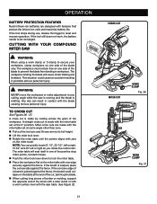
...MITER SAW WARNING: When using a work clamp or C-clamp to secure your workpiece, clamp workpiece on one edge securely against the fence. If the board is placed against the fence. See Figure 32. 21 CROSS CUT 45 miter CUT work , the battery needs to be recharged. OPERATION BATTERY PROTECTION FEATURES Ryobi...an accident resulting in workpiece. If the tool stops during use, release the trigger to any cutting angle while the saw table. This situation could collapse on the miter scale. Any slip can quickly locate 0°, 15°, 22-1/2°, left or right, 31.62° ...
...MITER SAW WARNING: When using a work clamp or C-clamp to secure your workpiece, clamp workpiece on one edge securely against the fence. If the board is placed against the fence. See Figure 32. 21 CROSS CUT 45 miter CUT work , the battery needs to be recharged. OPERATION BATTERY PROTECTION FEATURES Ryobi...an accident resulting in workpiece. If the tool stops during use, release the trigger to any cutting angle while the saw table. This situation could collapse on the miter scale. Any slip can quickly locate 0°, 15°, 22-1/2°, left or right, 31.62° ...
User Manual
Page 26
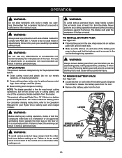
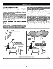
...90° inside corner Top edge against fence = LEFT SIDE, INSIDE CORNER RIGHT SIDE, OUTSIDE CORNER MITER Table Fence outside corner, lay the molding with extreme accuracy. OPERATION cutting crown molding This compound miter saw . 52° 38° ceiling w a l l Fence inside or outside corner BOTTOM edge... molding are interdependent; changing one angle changes the other tool made. The two contact surfaces on miter table 26 Fig. 33 In general, compound miter saws do not have angles of cutting crown molding. The crown molding is very easy for compound...
...90° inside corner Top edge against fence = LEFT SIDE, INSIDE CORNER RIGHT SIDE, OUTSIDE CORNER MITER Table Fence outside corner, lay the molding with extreme accuracy. OPERATION cutting crown molding This compound miter saw . 52° 38° ceiling w a l l Fence inside or outside corner BOTTOM edge... molding are interdependent; changing one angle changes the other tool made. The two contact surfaces on miter table 26 Fig. 33 In general, compound miter saws do not have angles of cutting crown molding. The crown molding is very easy for compound...
User Manual
Page 28
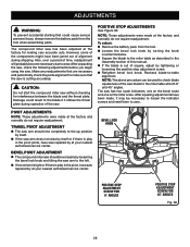
... blade squareness of time, readjustment will probably become necessary due to -table alignment. Also, over a period of the saw blade to zero. CAUTION: Do not start the compound miter saw without checking for making very accurate cuts. POSITIVE STOP ADJUSTMENTS See Figure 36. Recheck blade-to wear. The compound... miter saw has been adjusted at the factory and normally do not require readjustment. Make any readjustments that are necessary and periodically check ...
... blade squareness of time, readjustment will probably become necessary due to -table alignment. Also, over a period of the saw blade to zero. CAUTION: Do not start the compound miter saw without checking for making very accurate cuts. POSITIVE STOP ADJUSTMENTS See Figure 36. Recheck blade-to wear. The compound... miter saw has been adjusted at the factory and normally do not require readjustment. Make any readjustments that are necessary and periodically check ...
User Manual
Page 32
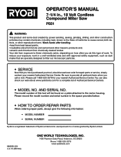
...MODEL NO. AND SERIAL NO. Please record the model number and serial number in ., 18 Volt Cordless Compound Miter Saw P551 WARNING: This product and some dust created by Ryobi Limited. 988000-224 4-2-13 (REV:04) ONE WORLD TECHNOLOGIES, INC. 1428 Pearman Dairy Road, Anderson, SC...repair parts, always give the following information: • MODEL NUMBER • SERIAL NUMBER Ryobi is a registered trademark of Ryobi Limited and is used pursuant to a license granted by power sanding, sawing, grinding, drilling, and other construction activities may contain chemicals, including lead, known to...
...MODEL NO. AND SERIAL NO. Please record the model number and serial number in ., 18 Volt Cordless Compound Miter Saw P551 WARNING: This product and some dust created by Ryobi Limited. 988000-224 4-2-13 (REV:04) ONE WORLD TECHNOLOGIES, INC. 1428 Pearman Dairy Road, Anderson, SC...repair parts, always give the following information: • MODEL NUMBER • SERIAL NUMBER Ryobi is a registered trademark of Ryobi Limited and is used pursuant to a license granted by power sanding, sawing, grinding, drilling, and other construction activities may contain chemicals, including lead, known to...
User Manual 4
Page 3
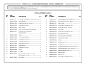
... Bearing Holder Plate 1 Gear and Spindle Assembly 1 Compression Spring 1 E-Ring 1 Spindle Lock Pin 1 O-Ring 1 Armature Assembly (Inc. COMPOUND MITER SAW or when ordering parts. NUMBER DESCRIPTION PARTS LIST FOR FIGURE A QTY KEY PART NO. Key No. 2 1 Warning Label 1 Screw (M5 ...CM/5C 1 Ball Bearing (608 2RS C3 1 Hex Nut (M4 4 Front cover 1 Screw (M4 x 20 mm, Pan Hd 4 3 COMPOUND MITER SAW - Always mention the model number in all correspondence regarding your 7-1/4 in . NUMBER DESCRIPTION QTY 1 080001020711 2 080001020902 3 089240001052 4 089240001093 5 089240001065 6...
... Bearing Holder Plate 1 Gear and Spindle Assembly 1 Compression Spring 1 E-Ring 1 Spindle Lock Pin 1 O-Ring 1 Armature Assembly (Inc. COMPOUND MITER SAW or when ordering parts. NUMBER DESCRIPTION PARTS LIST FOR FIGURE A QTY KEY PART NO. Key No. 2 1 Warning Label 1 Screw (M5 ...CM/5C 1 Ball Bearing (608 2RS C3 1 Hex Nut (M4 4 Front cover 1 Screw (M4 x 20 mm, Pan Hd 4 3 COMPOUND MITER SAW - Always mention the model number in all correspondence regarding your 7-1/4 in . NUMBER DESCRIPTION QTY 1 080001020711 2 080001020902 3 089240001052 4 089240001093 5 089240001065 6...
User Manual 4
Page 4
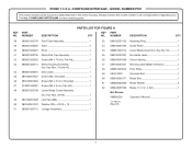
... 581410003 60 089240001071 61 080009002060 62 089240001909 Not Shown: 988000224 11-18-10 (Rev:01) Retaining Ring 1 Guide Roller 1 Lower Blade Guard (Inc. COMPOUND MITER SAW - COMPOUND MITER SAW or when ordering parts. NUMBER DESCRIPTION QTY 38 080001020704 Field Tube Assembly 1 39 080001020026 Tube 4 40 080001020027 Rivet 4 41 080001020705 Motor End Cap Assembly 1 42...
... 581410003 60 089240001071 61 080009002060 62 089240001909 Not Shown: 988000224 11-18-10 (Rev:01) Retaining Ring 1 Guide Roller 1 Lower Blade Guard (Inc. COMPOUND MITER SAW - COMPOUND MITER SAW or when ordering parts. NUMBER DESCRIPTION QTY 38 080001020704 Field Tube Assembly 1 39 080001020026 Tube 4 40 080001020027 Rivet 4 41 080001020705 Motor End Cap Assembly 1 42...
User Manual 4
Page 6
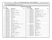
...Laser Bracket 1 Washer (ID4.2 x OD10 x 1t 2 Screw (M4 x 12 mm, Pan Hd 2 Screw (M8 x 10 mm, Hex Soc. RYOBI 7-1/4 in . COMPOUND MITER SAW - Hd 1 080001020016 Tension Spring 1 40 089240001076 Blade Wrench (Hex Key, M5 1 089240001034 Spring Spacer 1 41 089100207013 Grommet 1 089240001024 Lock Pin 1... 52 089240001003 53 080006014002 54 089240001084 55 089240001010 56 089240001009 57 080001020004 58 089240001008 59 089240001007 60 080001020709 Base Assembly (Inc. COMPOUND MITER SAW or when ordering parts. Key Nos. 48-49 1 No Hands Label 2 No Hand Label 2 Steel Ball (8 mm 1 ...
...Laser Bracket 1 Washer (ID4.2 x OD10 x 1t 2 Screw (M4 x 12 mm, Pan Hd 2 Screw (M8 x 10 mm, Hex Soc. RYOBI 7-1/4 in . COMPOUND MITER SAW - Hd 1 080001020016 Tension Spring 1 40 089240001076 Blade Wrench (Hex Key, M5 1 089240001034 Spring Spacer 1 41 089100207013 Grommet 1 089240001024 Lock Pin 1... 52 089240001003 53 080006014002 54 089240001084 55 089240001010 56 089240001009 57 080001020004 58 089240001008 59 089240001007 60 080001020709 Base Assembly (Inc. COMPOUND MITER SAW or when ordering parts. Key Nos. 48-49 1 No Hands Label 2 No Hand Label 2 Steel Ball (8 mm 1 ...
User Manual 4
Page 7
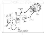
MODEL NUMBER P551 LASER SWITCH RED LEAD BLACK LEAD JACK BLACK BRUSH LEAD WHITE LEAD MOTOR RED LEAD SWITCH RED BRUSH LEAD LASER WIRING DIAGRAM 7 RYOBI 7-1/4 in. COMPOUND MITER SAW -
MODEL NUMBER P551 LASER SWITCH RED LEAD BLACK LEAD JACK BLACK BRUSH LEAD WHITE LEAD MOTOR RED LEAD SWITCH RED BRUSH LEAD LASER WIRING DIAGRAM 7 RYOBI 7-1/4 in. COMPOUND MITER SAW -


