User Manual
Page 2
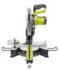
...; Warranty...2 General Safety Rules...3-4 Specific Safety Rules...4-5 Symbols...6 Glossary of Terms...7 Features...8-10 Tools Needed...10 Loose Parts List...11 Assembly...12-19 Operation...20-27 Adjustments...28-29 Maintenance...30 Parts Ordering / Service...Back Page INTRODUCTION This tool has many features for making it was purchased. The replacement power tool will do so without any RYOBI...
...; Warranty...2 General Safety Rules...3-4 Specific Safety Rules...4-5 Symbols...6 Glossary of Terms...7 Features...8-10 Tools Needed...10 Loose Parts List...11 Assembly...12-19 Operation...20-27 Adjustments...28-29 Maintenance...30 Parts Ordering / Service...Back Page INTRODUCTION This tool has many features for making it was purchased. The replacement power tool will do so without any RYOBI...
User Manual
Page 3
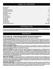
... of operation. KEEP BLADES CLEAN, SHARP, and with incorrect size holes. Never use of your hand and frees both hands to operate the tool. DO NOT OVERREACH. Serious injury could ignite fumes. Keep TOOL dry, clean, and free from oil and grease. A guard or other part that is damaged must be properly repaired or replaced by an authorized service center to follow all instructions listed below...
... of operation. KEEP BLADES CLEAN, SHARP, and with incorrect size holes. Never use of your hand and frees both hands to operate the tool. DO NOT OVERREACH. Serious injury could ignite fumes. Keep TOOL dry, clean, and free from oil and grease. A guard or other part that is damaged must be properly repaired or replaced by an authorized service center to follow all instructions listed below...
User Manual
Page 4
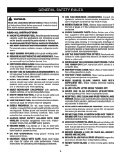
... saw arm (bevel function) by qualified repair personnel using only identical replacement parts. If a work or in blade cutting path with hands and fingers for one workpiece on the miter table and position it away from other metal objects like paper clips, coins, keys, nails, screws, or other small metal objects that the safety of blade pinching and kickback. Inserting the battery pack into power tools that is suitabe for any adjustments, changing accessories...
... saw arm (bevel function) by qualified repair personnel using only identical replacement parts. If a work or in blade cutting path with hands and fingers for one workpiece on the miter table and position it away from other metal objects like paper clips, coins, keys, nails, screws, or other small metal objects that the safety of blade pinching and kickback. Inserting the battery pack into power tools that is suitabe for any adjustments, changing accessories...
User Manual
Page 5
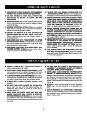
... blade and its cutting path with safe operation BEFORE performing any work and that no obstructions will interfere with your hands and fingers for any electrical component fail to perform properly, shut off tool and wait for saw blade to stop . b) Keep hands out of path of the saw blade. ALWAYS release the power switch and allow the saw blade. f) Turn off the power switch, remove the miter saw arm, moving workpiece or changing settings...
... blade and its cutting path with safe operation BEFORE performing any work and that no obstructions will interfere with your hands and fingers for any electrical component fail to perform properly, shut off tool and wait for saw blade to stop . b) Keep hands out of path of the saw blade. ALWAYS release the power switch and allow the saw blade. f) Turn off the power switch, remove the miter saw arm, moving workpiece or changing settings...
User Manual
Page 7
... reference to the table surface. Heel Alignment of the blade. Kerf The material removed by the blade in a through cut made with the blade. This aid helps keep the operator's hands well away from the blade. Push Blocks (flooring and table saws) Device used to the fence. Resin A sticky, sap-based substance that the tip of the saw during any ripping operation. Bevel Cut A cutting operation made with adjustable blades or knives. Gum...
... reference to the table surface. Heel Alignment of the blade. Kerf The material removed by the blade in a through cut made with the blade. This aid helps keep the operator's hands well away from the blade. Push Blocks (flooring and table saws) Device used to the fence. Resin A sticky, sap-based substance that the tip of the saw during any ripping operation. Bevel Cut A cutting operation made with adjustable blades or knives. Gum...
User Manual
Page 8
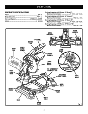
...Capacity with Miter at 45°/Bevel 0°: Maximum lumber sizes 1-1/2 in . Cutting Capacity with Miter at 45°/Bevel 45°: Maximum lumber sizes 1-1/2 in . Miter Lock lever BLADE WRENCH Dust BAG Upper Blade Guard "D" handle switch lock Switch Trigger laser guide Bevel Lock Knob Lower blade guard "NO HANDS ZONE" BOUNDARY LINE 45 30 33.9 15 0 1 2 3 4 5 "NO HANDS ZONE" LABEL bevel scale miter fence base 45 MITER TABLE WORK CLAMP 8 Miter Scale throat plate Fig. 1 x 3 in . No Load Speed 4,500 r/min. (RPM) Motor 18 Volt DC Cutting Capacity with...
...Capacity with Miter at 45°/Bevel 0°: Maximum lumber sizes 1-1/2 in . Cutting Capacity with Miter at 45°/Bevel 45°: Maximum lumber sizes 1-1/2 in . Miter Lock lever BLADE WRENCH Dust BAG Upper Blade Guard "D" handle switch lock Switch Trigger laser guide Bevel Lock Knob Lower blade guard "NO HANDS ZONE" BOUNDARY LINE 45 30 33.9 15 0 1 2 3 4 5 "NO HANDS ZONE" LABEL bevel scale miter fence base 45 MITER TABLE WORK CLAMP 8 Miter Scale throat plate Fig. 1 x 3 in . No Load Speed 4,500 r/min. (RPM) Motor 18 Volt DC Cutting Capacity with...
User Manual
Page 9
... 4-1/4 in . BEVEL LOCK KNOB The bevel lock knob securely locks your compound miter saw 's base. A storage area for making all operating features and safety rules. 7-1/4 in . The spindle lock button locks the spindle stopping the blade from each side of the saw arm by depressing the lock pin. Positive stop adjustment screws have been provided on . BLADE WRENCH STORAGE See Figure 1. One end of the blade. Use the hex key end when installing or removing blade and the phillips end when removing or loosening screws. MITER LOCK lever See...
... 4-1/4 in . BEVEL LOCK KNOB The bevel lock knob securely locks your compound miter saw 's base. A storage area for making all operating features and safety rules. 7-1/4 in . The spindle lock button locks the spindle stopping the blade from each side of the saw arm by depressing the lock pin. Positive stop adjustment screws have been provided on . BLADE WRENCH STORAGE See Figure 1. One end of the blade. Use the hex key end when installing or removing blade and the phillips end when removing or loosening screws. MITER LOCK lever See...
User Manual
Page 12
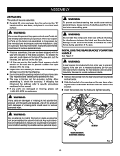
... saw has been shipped with the saw arm secured in a hazardous condition leading to the product by the handle. Hand pressure should remain on a level work surface or stand. Remove the screws from the rear bracket/carrying handle and set for use this miter saw to prevent sudden rise upon release of the saw. ASSEMBLY UNPACKING This product requires assembly. Carefully lift miter saw base from the tool when assembling parts...
... saw has been shipped with the saw arm secured in a hazardous condition leading to the product by the handle. Hand pressure should remain on a level work surface or stand. Remove the screws from the rear bracket/carrying handle and set for use this miter saw to prevent sudden rise upon release of the saw. ASSEMBLY UNPACKING This product requires assembly. Carefully lift miter saw base from the tool when assembling parts...
User Manual
Page 15
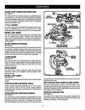
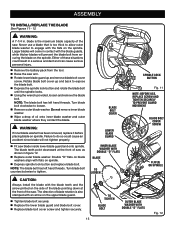
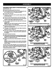
...; Tighten blade bolt securely. Replace the lower blade guard and blade bolt cover. Replace blade bolt cover screw and tighten securely. 15 To Tighten Blade BOLT 45 Outer Blade Washer WITH DOUBLE "D" FLATS Fig. 12 blade is too thick to allow outer blade washer to expose the blade bolt. Depress the spindle lock button and rotate the blade bolt until the spindle locks. Using the wrench provided, loosen and remove the blade bolt. ASSEMBLY To Install/replace...
...; Tighten blade bolt securely. Replace the lower blade guard and blade bolt cover. Replace blade bolt cover screw and tighten securely. 15 To Tighten Blade BOLT 45 Outer Blade Washer WITH DOUBLE "D" FLATS Fig. 12 blade is too thick to allow outer blade washer to expose the blade bolt. Depress the spindle lock button and rotate the blade bolt until the spindle locks. Using the wrench provided, loosen and remove the blade bolt. ASSEMBLY To Install/replace...
User Manual
Page 16
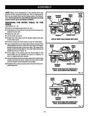
... the compound miter saw arm. Lift the miter lock lever. Rotate the miter table until the square and throat plate are needed. Using the blade wrench provided, loosen the socket head screws securing the fence. MITER FENCE framing square MITER TABLE Miter lock lever pointer throat plate VIEW OF MITER TABLE SQUARE WITH FENCE Fig. 13 MITER FENCE MITER TABLE framing square throat plate VIEW OF MITER TABLE NOT SQUARE WITH FENCE, ADJUSTMENTS ARE REQUIRED Fig. 14 MITER FENCE MITER TABLE framing square throat plate VIEW OF MITER TABLE NOT SQUARE WITH FENCE...
... the compound miter saw arm. Lift the miter lock lever. Rotate the miter table until the square and throat plate are needed. Using the blade wrench provided, loosen the socket head screws securing the fence. MITER FENCE framing square MITER TABLE Miter lock lever pointer throat plate VIEW OF MITER TABLE SQUARE WITH FENCE Fig. 13 MITER FENCE MITER TABLE framing square throat plate VIEW OF MITER TABLE NOT SQUARE WITH FENCE, ADJUSTMENTS ARE REQUIRED Fig. 14 MITER FENCE MITER TABLE framing square throat plate VIEW OF MITER TABLE NOT SQUARE WITH FENCE...
User Manual
Page 17
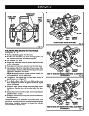
... or back edge of the square and the saw arm in figures 18 and 19, adjustments are needed. Using the blade wrench, loosen the socket head screws that secure the miter fence to the miter table. Place one on the miter table. MITER FENCE Blade MITER framing TABLE square VIEW OF Blade NOT SQUARE WITh FENCE, ADJUSTMENTS ARE REQUIRED Fig. 18 MITER FENCE Blade MITER framing TABLE square VIEW OF Blade NOT SQUARE WITH FENCE, ADJUSTMENTS ARE REQUIRED Fig. 19 17 Socket Head Screw(s) ASSEMBLY Socket Head Screw(s) Miter lock lever MITER FENCE 45 31...
... or back edge of the square and the saw arm in figures 18 and 19, adjustments are needed. Using the blade wrench, loosen the socket head screws that secure the miter fence to the miter table. Place one on the miter table. MITER FENCE Blade MITER framing TABLE square VIEW OF Blade NOT SQUARE WITh FENCE, ADJUSTMENTS ARE REQUIRED Fig. 18 MITER FENCE Blade MITER framing TABLE square VIEW OF Blade NOT SQUARE WITH FENCE, ADJUSTMENTS ARE REQUIRED Fig. 19 17 Socket Head Screw(s) ASSEMBLY Socket Head Screw(s) Miter lock lever MITER FENCE 45 31...
User Manual
Page 18
... 23, adjustments are needed. Loosen the bevel lock knob. Adjust positive stop adjustment screw to miter table). Note: Make sure that the square contacts the flat part of the saw blade, not the blade teeth. Rotate the blade by hand and check the blade-to-table alignment at several points. The edge of the square and the saw blade should be used to check blade squareness of the saw blade to the miter table at 0° bevel (blade set saw blade. Note...
... 23, adjustments are needed. Loosen the bevel lock knob. Adjust positive stop adjustment screw to miter table). Note: Make sure that the square contacts the flat part of the saw blade, not the blade teeth. Rotate the blade by hand and check the blade-to-table alignment at several points. The edge of the square and the saw blade should be used to check blade squareness of the saw blade to the miter table at 0° bevel (blade set saw blade. Note...
User Manual
Page 20
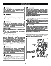
... with groove inside saw to do so could result in objects being thrown into your Ryobi One+ battery pack and charger models. APPLICATIONS This product has been designed only for picture frames mold- Depress the latches to do not cut . DEPRESS LATCHES TO RELEASE BATTERY PACK WARNING: To avoid serious personal injury, always lock the miter lock lever before beginning operation. LATCHES WARNING: Before...
... with groove inside saw to do so could result in objects being thrown into your Ryobi One+ battery pack and charger models. APPLICATIONS This product has been designed only for picture frames mold- Depress the latches to do not cut . DEPRESS LATCHES TO RELEASE BATTERY PACK WARNING: To avoid serious personal injury, always lock the miter lock lever before beginning operation. LATCHES WARNING: Before...
User Manual
Page 21
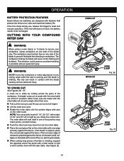
... the miter table set at some angle other than zero. Pull out the lock pin and lift saw arm to its full height. Lift the miter lock lever. Rotate the miter table until the pointer aligns with zero on the blade at the end of the cut See Figures 26 - 27. If the tool stops during use, release the trigger to any cutting angle while the saw table. CUTTING WITH YOUR Compound MITER SAW...
... the miter table set at some angle other than zero. Pull out the lock pin and lift saw arm to its full height. Lift the miter lock lever. Rotate the miter table until the pointer aligns with zero on the blade at the end of the cut See Figures 26 - 27. If the tool stops during use, release the trigger to any cutting angle while the saw table. CUTTING WITH YOUR Compound MITER SAW...

User Manual
Page 22
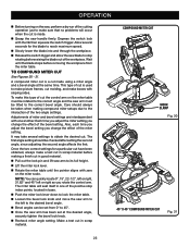
... with edge of saw blade. Grasp the stock firmly with one hand and secure it against the fence. Use the optional work clamp or a C-clamp to secure the workpiece when possible. Before turning on the miter table with thumb then squeeze the switch trigger. Allow several seconds for the desired angle. Once the saw arm has been set at the desired angle, securely tighten the bevel lock knob. ...
... with edge of saw blade. Grasp the stock firmly with one hand and secure it against the fence. Use the optional work clamp or a C-clamp to secure the workpiece when possible. Before turning on the miter table with thumb then squeeze the switch trigger. Allow several seconds for the desired angle. Once the saw arm has been set at the desired angle, securely tighten the bevel lock knob. ...
User Manual
Page 23
... from 0° to 45°. Once the saw arm has been set from the miter table. The miter table will occur when the cut is a cut in base. Push the miter lock lever down to lock the miter table. Loosen the bevel lock knob and move the saw blade to its full height. Lift the miter lock lever. Rotate the miter table until the blade stops before making compound miter setups due to the correct bevel angle.
... from 0° to 45°. Once the saw arm has been set from the miter table. The miter table will occur when the cut is a cut in base. Push the miter lock lever down to lock the miter table. Loosen the bevel lock knob and move the saw blade to its full height. Lift the miter lock lever. Rotate the miter table until the blade stops before making compound miter setups due to the correct bevel angle.
User Manual
Page 29
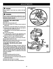
...; Set miter and bevel angles to 0º. Use the work clamp or a C-clamp to secure a piece of scrap wood. Turn the saw on the left or right until properly aligned. To adjust: Remove the battery pack from the tool. Push the miter lock lever fully down should be required to your nearest Ryobi Authorized Service Center for repair. Avoid direct eye contact with light source. laser adjustment screw WARNING: Use of controls or adjustments...
...; Set miter and bevel angles to 0º. Use the work clamp or a C-clamp to secure a piece of scrap wood. Turn the saw on the left or right until properly aligned. To adjust: Remove the battery pack from the tool. Push the miter lock lever fully down should be required to your nearest Ryobi Authorized Service Center for repair. Avoid direct eye contact with light source. laser adjustment screw WARNING: Use of controls or adjustments...
User Manual
Page 30
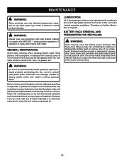
... damaged by their use only identical replacement parts. WARNING: Do not at any other parts may result in contact with heavy-duty adhesive tape. BATTERY PACK REMOVAL AND PREPARATION FOR RECYCLING WARNING: Upon removal, cover the battery pack's terminals with plastic parts. Electric tools used on these materials, it is extremely important to comply with any of properly. MAINTENANCE WARNING: When servicing, use . WARNING: Always...
... damaged by their use only identical replacement parts. WARNING: Do not at any other parts may result in contact with heavy-duty adhesive tape. BATTERY PACK REMOVAL AND PREPARATION FOR RECYCLING WARNING: Upon removal, cover the battery pack's terminals with plastic parts. Electric tools used on these materials, it is extremely important to comply with any of properly. MAINTENANCE WARNING: When servicing, use . WARNING: Always...
User Manual 4
Page 3
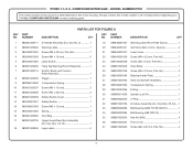
...;成紙 (Pivot Plate Screw 1 Set Screw (M4 x 8 mm, Nylock 2 Laser Cover 1 Screw (M4 x 22 mm, Pan Hd 1 Screw (M4 x 8 mm, Pan Hd 1 Stop Block 1 Screw (M4 x 18 mm, Pan Hd 2 Bearing Holder Plate 1 Gear and Spindle Assembly 1 Compression Spring 1 E-Ring 1 Spindle Lock Pin 1 O-Ring 1 Armature Assembly (Inc. Key Nos. 33-34)..... 1 Ball Bearing (6200 TU/TZ/CM/5C 1 Ball Bearing (608 2RS C3 1 Hex Nut (M4 4 Front cover 1 Screw (M4 x 20...
...;成紙 (Pivot Plate Screw 1 Set Screw (M4 x 8 mm, Nylock 2 Laser Cover 1 Screw (M4 x 22 mm, Pan Hd 1 Screw (M4 x 8 mm, Pan Hd 1 Stop Block 1 Screw (M4 x 18 mm, Pan Hd 2 Bearing Holder Plate 1 Gear and Spindle Assembly 1 Compression Spring 1 E-Ring 1 Spindle Lock Pin 1 O-Ring 1 Armature Assembly (Inc. Key Nos. 33-34)..... 1 Ball Bearing (6200 TU/TZ/CM/5C 1 Ball Bearing (608 2RS C3 1 Hex Nut (M4 4 Front cover 1 Screw (M4 x 20...
User Manual 4
Page 6
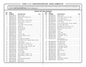
... Soc. Hd.)...... 1 Laser Bracket 1 Washer (ID4.2 x OD10 x 1t 2 Screw (M4 x 12 mm, Pan Hd 2 Screw (M8 x 10 mm, Hex Soc. MODEL NUMBER P551 The model number will be found on a label attached to the motor housing. Key Nos. 48-49 1 No Hands Label 2 No Hand Label 2 Steel Ball (8 mm 1 Compression Spring 1 Screw (M5 x 18 mm 2 Wear Ring 8 Miter Lock Tip 1 Plug 1 Miter Lock Shaft 1 Miter Lock Lever 1 Spring 1 Screw (M5, Shoulder 1 Work Clamp 1 089240001015 Miter Pointer 1 6
... Soc. Hd.)...... 1 Laser Bracket 1 Washer (ID4.2 x OD10 x 1t 2 Screw (M4 x 12 mm, Pan Hd 2 Screw (M8 x 10 mm, Hex Soc. MODEL NUMBER P551 The model number will be found on a label attached to the motor housing. Key Nos. 48-49 1 No Hands Label 2 No Hand Label 2 Steel Ball (8 mm 1 Compression Spring 1 Screw (M5 x 18 mm 2 Wear Ring 8 Miter Lock Tip 1 Plug 1 Miter Lock Shaft 1 Miter Lock Lever 1 Spring 1 Screw (M5, Shoulder 1 Work Clamp 1 089240001015 Miter Pointer 1 6


