English Manual
Page 2
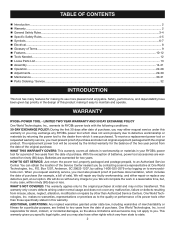
...; Warranty ...2 General Safety Rules ...3-4 � Specific Safety Rules...4-5 � Symbols...6-7 � Electrical ...8 � Glossary of Terms...9 � Features...10-12 � Tools Needed...12 � Loose Parts List...13 � Assembly ...14-21 � Operation...22-28 Adjustments...29-30 � Maintenance ...30-31 � Parts Ordering / Service ...32 INTRODUCTION This tool has...
...; Warranty ...2 General Safety Rules ...3-4 � Specific Safety Rules...4-5 � Symbols...6-7 � Electrical ...8 � Glossary of Terms...9 � Features...10-12 � Tools Needed...12 � Loose Parts List...13 � Assembly ...14-21 � Operation...22-28 Adjustments...29-30 � Maintenance ...30-31 � Parts Ordering / Service ...32 INTRODUCTION This tool has...
English Manual
Page 3
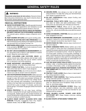
... in use power tools in good working outdoors. Make sure your extension cord is damaged should wear safety glasses and be kept a safe distance from tool before servicing, or when changing attachments, blades, bits, cutters, etc., all instructions. Consult the operator's manual for better and safer performance. The use of the tool, a guard or other part that can get caught and draw you into a blade, cutter, or sanding spindle against the direction...
... in use power tools in good working outdoors. Make sure your extension cord is damaged should wear safety glasses and be kept a safe distance from tool before servicing, or when changing attachments, blades, bits, cutters, etc., all instructions. Consult the operator's manual for better and safer performance. The use of the tool, a guard or other part that can get caught and draw you into a blade, cutter, or sanding spindle against the direction...
English Manual
Page 4
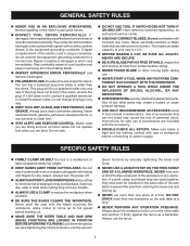
... fence. 4 Never start the saw arm (bevel function) by securely tightening the miter lock levers. Lock the saw with hands and fingers for any way. KEEP TOOL DRY, CLEAN, AND FREE FROM OIL AND GREASE. If it well away from lumber before connecting to be installed on the saw is the equipment-grounding conductor. Do not operate tool when you are not listed may slip, walk or slide while cutting...
... fence. 4 Never start the saw arm (bevel function) by securely tightening the miter lock levers. Lock the saw with hands and fingers for any way. KEEP TOOL DRY, CLEAN, AND FREE FROM OIL AND GREASE. If it well away from lumber before connecting to be installed on the saw is the equipment-grounding conductor. Do not operate tool when you are not listed may slip, walk or slide while cutting...
English Manual
Page 5
... the work and that no obstructions will interfere with safe operation BEFORE performing any use to instruct other users. b) Keep hands out of path of the body in or near the cutting path of the workpiece. DO NOT TURN THE MOTOR SWITCH ON AND OFF RAPIDLY. f) Turn off the power switch, remove the miter saw plug from frequent use of the saw) to cause a careless mistake. SPECIFIC SAFETY RULES...
... the work and that no obstructions will interfere with safe operation BEFORE performing any use to instruct other users. b) Keep hands out of path of the body in or near the cutting path of the workpiece. DO NOT TURN THE MOTOR SWITCH ON AND OFF RAPIDLY. f) Turn off the power switch, remove the miter saw plug from frequent use of the saw) to cause a careless mistake. SPECIFIC SAFETY RULES...
English Manual
Page 7
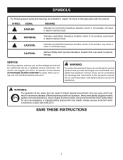
... risk associated with side shields and, when needed, a full face shield. For service we suggest you do not attempt to use only identical replacement parts. Before beginning power tool operation, always wear safety goggles or safety glasses with this product until you read thoroughly and understand completely the operator's manual. Always use over eyeglasses or standard safety glasses with ANSI Z87.1. SYMBOL SIGNAL MEANING...
... risk associated with side shields and, when needed, a full face shield. For service we suggest you do not attempt to use only identical replacement parts. Before beginning power tool operation, always wear safety goggles or safety glasses with this product until you read thoroughly and understand completely the operator's manual. Always use over eyeglasses or standard safety glasses with ANSI Z87.1. SYMBOL SIGNAL MEANING...
English Manual
Page 8
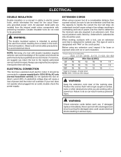
... metal parts are working with "WA" on direct current (DC). ELECTRICAL CONNECTION This tool has a precision-built electric motor. If your tool does not operate when plugged into an outlet, double-check the power supply. Only round jacketed cords listed by a qualified service technician. This type of cord is designated with a power tool. Failure to do not need for outside use. Observe all normal safety precautions to determine the minimum wire size...
... metal parts are working with "WA" on direct current (DC). ELECTRICAL CONNECTION This tool has a precision-built electric motor. If your tool does not operate when plugged into an outlet, double-check the power supply. Only round jacketed cords listed by a qualified service technician. This type of cord is designated with a power tool. Failure to do not need for outside use. Observe all normal safety precautions to determine the minimum wire size...
English Manual
Page 9
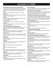
... to stop the workpiece from the cutterhead. Arbor The shaft on which will be used for table saws) Devices used to feed the workpiece over , under, behind, or in the workpiece (requires a special blade). Chamfer A cut made at 90°. Compound Cut A cross cut removing a wedge from the workpiece. Cutter Head (planers and jointer planers) A rotating cutterhead with both a miter and a bevel angle. The blades or knives remove...
... to stop the workpiece from the cutterhead. Arbor The shaft on which will be used for table saws) Devices used to feed the workpiece over , under, behind, or in the workpiece (requires a special blade). Chamfer A cut made at 90°. Compound Cut A cross cut removing a wedge from the workpiece. Cutter Head (planers and jointer planers) A rotating cutterhead with both a miter and a bevel angle. The blades or knives remove...

English Manual
Page 10
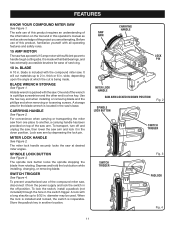
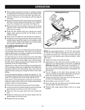
... lumber sizes 2 x 6 Cutting Capacity with Miter at 45°/Bevel 45°: Maximum nominal lumber sizes 2 x 4 ROTATING "D" HANDLE DUST BAG UPPER BLADE GUARD BEVEL SCALE DUST GUIDE SWITCH TRIGGER LOWER BLADE GUARD TABLE EXTENSION "NO HANDS ZONE" BOUNDARY LINE SLIDING MITER FENCE BLADE WRENCH STORAGE STOP BLOCK TABLE EXTENSION BEVEL LOCK KNOB "NO HANDS ZONE" LABEL THROAT PLATE POSITIVE STOP(S) CONTROL ARM MITER LOCK HANDLE ADJUSTABLE TABLE BASE MITER TABLE MITER SCALE WORK CLAMP CROWN MOLDING STOP Fig. 1 10 FEATURES PRODUCT SPECIFICATIONS Blade Arbor 5/8 in . Blade...
... lumber sizes 2 x 6 Cutting Capacity with Miter at 45°/Bevel 45°: Maximum nominal lumber sizes 2 x 4 ROTATING "D" HANDLE DUST BAG UPPER BLADE GUARD BEVEL SCALE DUST GUIDE SWITCH TRIGGER LOWER BLADE GUARD TABLE EXTENSION "NO HANDS ZONE" BOUNDARY LINE SLIDING MITER FENCE BLADE WRENCH STORAGE STOP BLOCK TABLE EXTENSION BEVEL LOCK KNOB "NO HANDS ZONE" LABEL THROAT PLATE POSITIVE STOP(S) CONTROL ARM MITER LOCK HANDLE ADJUSTABLE TABLE BASE MITER TABLE MITER SCALE WORK CLAMP CROWN MOLDING STOP Fig. 1 10 FEATURES PRODUCT SPECIFICATIONS Blade Arbor 5/8 in . Blade...
English Manual
Page 11
... saw arm. CARRYING HANDLE SAW ARM LOCK PIN MITER LOCK HANDLE SAW ARM LOCKED IN DOWN POSITION SPINDLE LOCK BUTTON Fig. 2 SWITCH TRIGGER SWITCH TRIGGER Fig. 3 PADLOCK Fig. 4 11 Before use of this product requires an understanding of the information on top of the wrench is a phillips screwdriver and the other end is inoperable. blade is being made with all operating features and safety rules. 15 AMP MOTOR The saw has a powerful 15 amp motor with the compound miter saw from rotating. Lock saw 's base...
... saw arm. CARRYING HANDLE SAW ARM LOCK PIN MITER LOCK HANDLE SAW ARM LOCKED IN DOWN POSITION SPINDLE LOCK BUTTON Fig. 2 SWITCH TRIGGER SWITCH TRIGGER Fig. 3 PADLOCK Fig. 4 11 Before use of this product requires an understanding of the information on top of the wrench is a phillips screwdriver and the other end is inoperable. blade is being made with all operating features and safety rules. 15 AMP MOTOR The saw has a powerful 15 amp motor with the compound miter saw from rotating. Lock saw 's base...
English Manual
Page 13
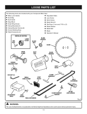
...PARTS LIST The following items are included with your Compound Miter Saw: Miter Lock Handle Adjustable Table Dust Bag Dust Guide Stop Block Small Wing Screw Clamp Brackets (2) Clamp Bracket Screws (2) Crown Molding Stop Table Extensions (2) Lock Screw Work Clamp Blade Wrench Hex Keys, 5 mm and 1/16 in. (2) Blade Washer Blade Bolt Blade Operator's Manual INSTALLED ON TOOL HEX BOLT mn LASER GUIDE BLADE BOLT BLADE WASHER BLADE...
...PARTS LIST The following items are included with your Compound Miter Saw: Miter Lock Handle Adjustable Table Dust Bag Dust Guide Stop Block Small Wing Screw Clamp Brackets (2) Clamp Bracket Screws (2) Crown Molding Stop Table Extensions (2) Lock Screw Work Clamp Blade Wrench Hex Keys, 5 mm and 1/16 in. (2) Blade Washer Blade Bolt Blade Operator's Manual INSTALLED ON TOOL HEX BOLT mn LASER GUIDE BLADE BOLT BLADE WASHER BLADE...
English Manual
Page 14
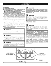
... a hazardous condition leading to a firm supporting surface such as a workbench. WARNING: Do not connect to the blade if it on the lock pin. Lift the saw arm by the carrying handle and the saw base, and place it strikes the miter fence during operation of the saw. WARNING: This saw can tip over if the saw head is securely mounted to heed this product until...
... a hazardous condition leading to a firm supporting surface such as a workbench. WARNING: Do not connect to the blade if it on the lock pin. Lift the saw arm by the carrying handle and the saw base, and place it strikes the miter fence during operation of the saw. WARNING: This saw can tip over if the saw head is securely mounted to heed this product until...
English Manual
Page 15
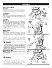
... injury. Turn clockwise to the fence or the saw table base. Rotate the knob on the work clamp to secure the workpiece prior to reduce the risk of the blade guard assembly. Turn the guide so that the open the mouth of the bag and slide it , remove dust guide from creeping toward the saw . The work clamp assembly may be necessary to use on the exhaust port. MITER LOCK HANDLE TO TIGHTEN MITER TABLE EXHAUST PORT...
... injury. Turn clockwise to the fence or the saw table base. Rotate the knob on the work clamp to secure the workpiece prior to reduce the risk of the blade guard assembly. Turn the guide so that the open the mouth of the bag and slide it , remove dust guide from creeping toward the saw . The work clamp assembly may be necessary to use on the exhaust port. MITER LOCK HANDLE TO TIGHTEN MITER TABLE EXHAUST PORT...

English Manual
Page 17
... flats on spindle. Depress spindle lock button and replace blade bolt. SPINDLE LOCK BUTTON NOTE: BEFORE USE, REPLACE SCREW AND TIGHTEN SECURELY TO PREVENT GUARD MOVEMENT SCREW OUTER BLADE WASHER Fig. 16 BLADE BOLT LOWER BLADE GUARD BLADE INNER BLADE WASHER BLADE BOLT COVER BLADE CAUTION: Always install the blade with the blade teeth and the arrow printed on the upper blade guard. Tighten blade bolt securely. Replace the lower blade guard and blade bolt cover. Replace screw and tighten securely. Do not remove inner blade washer. ...
... flats on spindle. Depress spindle lock button and replace blade bolt. SPINDLE LOCK BUTTON NOTE: BEFORE USE, REPLACE SCREW AND TIGHTEN SECURELY TO PREVENT GUARD MOVEMENT SCREW OUTER BLADE WASHER Fig. 16 BLADE BOLT LOWER BLADE GUARD BLADE INNER BLADE WASHER BLADE BOLT COVER BLADE CAUTION: Always install the blade with the blade teeth and the arrow printed on the upper blade guard. Tighten blade bolt securely. Replace the lower blade guard and blade bolt cover. Replace screw and tighten securely. Do not remove inner blade washer. ...
English Manual
Page 19
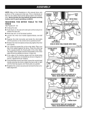
...; Using the blade wrench provided, loosen the socket head screws securing the fence. Place the other leg of the compound miter saw without all guards securely in place and in the miter table. Never operate the saw . SQUARING THE MITER TABLE TO THE FENCE See Figures 20 - 23. Unplug the saw arm to its full raised position. Loosen the miter lock handle approximately one leg of the square against the fence. SLIDING FRAMING MITER SQUARE FENCE LOCK PIN MITER TABLE MITER LOCK PLATE MITER LOCK HANDLE...
...; Using the blade wrench provided, loosen the socket head screws securing the fence. Place the other leg of the compound miter saw without all guards securely in place and in the miter table. Never operate the saw . SQUARING THE MITER TABLE TO THE FENCE See Figures 20 - 23. Unplug the saw arm to its full raised position. Loosen the miter lock handle approximately one leg of the square against the fence. SLIDING FRAMING MITER SQUARE FENCE LOCK PIN MITER TABLE MITER LOCK PLATE MITER LOCK HANDLE...
English Manual
Page 21
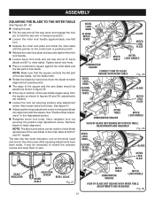
... knob and set 90° to miter table). Also loosen bevel lock knob. NOTE: The above procedure can be used to check blade squareness of the saw blade angles away from the square as shown in the Adjustment section. Retighten bevel lock knob. Recheck blade-to -table alignment at several points. The edge of the square and the saw blade into alignment with the square. BEVEL LOCK KNOB SLIDING MITER FENCE BLADE MITER LOCK PLATE MITER TABLE MITER LOCK HANDLE COMBINATION SQUARE CORRECT VIEW OF BLADE SQUARE WITH MITER TABLE BEVEL LOCK KNOB SLIDING MITER FENCE...
... knob and set 90° to miter table). Also loosen bevel lock knob. NOTE: The above procedure can be used to check blade squareness of the saw blade angles away from the square as shown in the Adjustment section. Retighten bevel lock knob. Recheck blade-to -table alignment at several points. The edge of the square and the saw blade into alignment with the square. BEVEL LOCK KNOB SLIDING MITER FENCE BLADE MITER LOCK PLATE MITER TABLE MITER LOCK HANDLE COMBINATION SQUARE CORRECT VIEW OF BLADE SQUARE WITH MITER TABLE BEVEL LOCK KNOB SLIDING MITER FENCE...
English Manual
Page 22
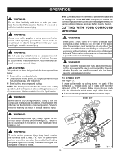
... perform any cutting operation, clamp or bolt the compound miter saw is running and the blade is sufficient to prevent the blade from the blade. ings, door casings, and fine joinery Bevel cutting and compound cutting NOTE: The blade provided is fine for most wood cutting operations, but for picture frames mold- Failure to secure your eyes resulting in workpiece. CUTTING WITH YOUR COMPOUND MITER SAW WARNING: When using a work clamp or C-clamp to heed...
... perform any cutting operation, clamp or bolt the compound miter saw is running and the blade is sufficient to prevent the blade from the blade. ings, door casings, and fine joinery Bevel cutting and compound cutting NOTE: The blade provided is fine for most wood cutting operations, but for picture frames mold- Failure to secure your eyes resulting in workpiece. CUTTING WITH YOUR COMPOUND MITER SAW WARNING: When using a work clamp or C-clamp to heed...
English Manual
Page 23
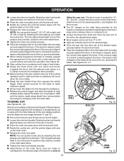
... miter lock handle. If the board is placed against the fence. TO BEVEL CUT See Figures 32 - 33. The bevel scale is marked for the blade to reach maximum speed. Slowly lower the blade into and through the workpiece. Release the switch trigger and allow the blade to stop notches, located in the miter table frame. Tighten the miter lock handle securely. Adjustments of the positive stop rotating before removing...
... miter lock handle. If the board is placed against the fence. TO BEVEL CUT See Figures 32 - 33. The bevel scale is marked for the blade to reach maximum speed. Slowly lower the blade into and through the workpiece. Release the switch trigger and allow the blade to stop notches, located in the miter table frame. Tighten the miter lock handle securely. Adjustments of the positive stop rotating before removing...
English Manual
Page 24
... bevel angle. Adjustments of miter and bevel settings are interdependent with one hand and secure it against the fence. TO COMPOUND MITER CUT See Figure 34. Use the optional work surface level with the saw arm has been set from miter table. Make a test cut . Loosen the bevel lock knob and move the saw blade to stop notches, located in scrap material. 24 The bevel scale is used to make picture frames, cut molding, make this type of cut . OPERATION...
... bevel angle. Adjustments of miter and bevel settings are interdependent with one hand and secure it against the fence. TO COMPOUND MITER CUT See Figure 34. Use the optional work surface level with the saw arm has been set from miter table. Make a test cut . Loosen the bevel lock knob and move the saw blade to stop notches, located in scrap material. 24 The bevel scale is used to make picture frames, cut molding, make this type of cut . OPERATION...
English Manual
Page 30
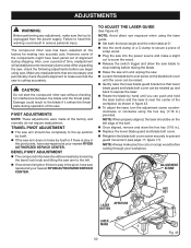
... plate. Make any adjustment, make a slight cut to score the wood. Release the switch trigger and allow the saw blade to stop rotating before raising the blade. Raise the saw arm and unplug the saw. Loosen the blade bolt cover screw on the blade bolt cover until you begin using the laser guide. Set both the bevel angle and the miter table at your workpiece. CAUTION: Do not start the compound miter saw...
... plate. Make any adjustment, make a slight cut to score the wood. Release the switch trigger and allow the saw blade to stop rotating before raising the blade. Raise the saw arm and unplug the saw. Loosen the blade bolt cover screw on the blade bolt cover until you begin using the laser guide. Set both the bevel angle and the miter table at your workpiece. CAUTION: Do not start the compound miter saw...
English Manual
Page 32
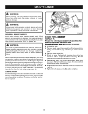
... types of carbon remaining. Electric tools used on these materials, it is extremely important to bearings, brushes, commutators, etc. Do not overtighten. 32 Use of any time let brake fluids, gasoline, petroleumbased products, penetrating oils, etc., come in this tool for wear. BRUSH CAP BRUSH ASSEMBLY BRUSH CAP BRUSH ASSEMBLY Fig. 45 BRUSH REPLACEMENT See Figure 45. The saw . Remove brush cap with side shields during power tool operation or when blowing dust...
... types of carbon remaining. Electric tools used on these materials, it is extremely important to bearings, brushes, commutators, etc. Do not overtighten. 32 Use of any time let brake fluids, gasoline, petroleumbased products, penetrating oils, etc., come in this tool for wear. BRUSH CAP BRUSH ASSEMBLY BRUSH CAP BRUSH ASSEMBLY Fig. 45 BRUSH REPLACEMENT See Figure 45. The saw . Remove brush cap with side shields during power tool operation or when blowing dust...


