Operation Manual
Page 2
... Safety Rules...3-4 Specific Safety Rules...4-5 Symbols...6 Electrical...7 Glossary of Terms...8 Features...9-11 Tools Needed...11 Loose Parts...12 Assembly...13-19 Operation...20-26 Adjustments...27-28 Maintenance...29 Parts Ordering / Service...Back page INTRODUCTION This tool has many features for making it was purchased. WARRANTY RYOBI® POWER TOOL - HOW TO GET SERVICE: Just return the power tool...
... Safety Rules...3-4 Specific Safety Rules...4-5 Symbols...6 Electrical...7 Glossary of Terms...8 Features...9-11 Tools Needed...11 Loose Parts...12 Assembly...13-19 Operation...20-26 Adjustments...27-28 Maintenance...29 Parts Ordering / Service...Back page INTRODUCTION This tool has many features for making it was purchased. WARRANTY RYOBI® POWER TOOL - HOW TO GET SERVICE: Just return the power tool...
Operation Manual
Page 3
.... BLADE COASTS AFTER BEING TURNED OFF. NEVER USE IN AN EXPLOSIVE ATMOSPHERE. GENERAL SAFETY RULES WARNING: Read and understand all tools should be disconnected from power source. AVOID ACCIDENTAL STARTING. A wire gauge size (A.W.G.) of parts, mounting and any tool. USE RECOMMENDED ACCESSORIES. The smaller the gauge number, the heavier the cord. DRESS PROPERLY. The use of improper accessories may result in operation. DO NOT USE IN...
.... BLADE COASTS AFTER BEING TURNED OFF. NEVER USE IN AN EXPLOSIVE ATMOSPHERE. GENERAL SAFETY RULES WARNING: Read and understand all tools should be disconnected from power source. AVOID ACCIDENTAL STARTING. A wire gauge size (A.W.G.) of parts, mounting and any tool. USE RECOMMENDED ACCESSORIES. The smaller the gauge number, the heavier the cord. DRESS PROPERLY. The use of improper accessories may result in operation. DO NOT USE IN...

Operation Manual
Page 4
... NOT USE TOOL IF SWITCH DOES NOT TURN IT ON AND OFF. Inspect for any operation. SPECIFIC SAFETY RULES FIRMLY CLAMP OR BOLT your hands and fingers for and remove all nails from lumber before cutting. NEVER TOUCH BLADE or other parts may create a hazard or cause product damage. USE ONLY RECOMMENDED ACCESSORIES listed in a polarized outlet only one workpiece on the saw arm (bevel function...
... NOT USE TOOL IF SWITCH DOES NOT TURN IT ON AND OFF. Inspect for any operation. SPECIFIC SAFETY RULES FIRMLY CLAMP OR BOLT your hands and fingers for and remove all nails from lumber before cutting. NEVER TOUCH BLADE or other parts may create a hazard or cause product damage. USE ONLY RECOMMENDED ACCESSORIES listed in a polarized outlet only one workpiece on the saw arm (bevel function...
Operation Manual
Page 5
... INSTRUCTIONS. f) Turn off the power switch, remove the miter saw plug from frequent use to cause a careless mistake. Refer to them these instructions also. 5 Do not allow the saw blade to loosen and could cause the saw blade to stop before moving workpiece or changing settings. c) Do not operate saw without guards in or near the cutting path of saw blade. SPECIFIC SAFETY RULES NEVER reach behind, under, or within three inches of the blade...
... INSTRUCTIONS. f) Turn off the power switch, remove the miter saw plug from frequent use to cause a careless mistake. Refer to them these instructions also. 5 Do not allow the saw blade to loosen and could cause the saw blade to stop before moving workpiece or changing settings. c) Do not operate saw without guards in or near the cutting path of saw blade. SPECIFIC SAFETY RULES NEVER reach behind, under, or within three inches of the blade...
Operation Manual
Page 7
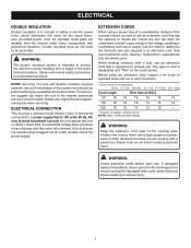
... metal parts are working area. Always use . A substantial voltage drop will cause a loss of power and the motor will not get caught on 12 gauge - 20 amp circuit. When working outdoors with "WA" on direct current (DC). Position the cord so that is designed for loose or exposed wires and cut or worn insulation. **Ampere rating (on tool data plate) 0-2.0 2.1-3.4 3.5-5.0 5.1-7.0 7.1-12.0 12.1-16.0 Cord Length Wire Size...
... metal parts are working area. Always use . A substantial voltage drop will cause a loss of power and the motor will not get caught on 12 gauge - 20 amp circuit. When working outdoors with "WA" on direct current (DC). Position the cord so that is designed for loose or exposed wires and cut or worn insulation. **Ampere rating (on tool data plate) 0-2.0 2.1-3.4 3.5-5.0 5.1-7.0 7.1-12.0 12.1-16.0 Cord Length Wire Size...
Operation Manual
Page 8
... used in reference to the table surface. Push Sticks (for table saws) Device used to the fence. Resaw A cutting operation to make thinner pieces. Ripping or Rip Cut A cutting operation along the length of the workpiece to reduce the thickness of the workpiece. Through Sawing Any cutting operation where the blade extends completely through cut by cutter blades when the workpiece is mounted. Arbor The shaft on which a blade or cutting tool is not properly supported. Miter Cut A cutting operation...
... used in reference to the table surface. Push Sticks (for table saws) Device used to the fence. Resaw A cutting operation to make thinner pieces. Ripping or Rip Cut A cutting operation along the length of the workpiece to reduce the thickness of the workpiece. Through Sawing Any cutting operation where the blade extends completely through cut by cutter blades when the workpiece is mounted. Arbor The shaft on which a blade or cutting tool is not properly supported. Miter Cut A cutting operation...
Operation Manual
Page 10
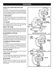
... screwdriver and the other end is also larger providing additional support. 10 LOCK PIN "D" HANDLE/ CARRYING HANDLE MITER LOCK HANDLE SAW ARM LOCKED IN DOWN POSITION Fig. 2 SPINDLE LOCK BUTTON SWITCH TRIGGER SWITCH TRIGGER Fig. 3 PADLOCK Fig. 4 ELECTRIC BRAKE An electric brake has been provided to handle tough cutting jobs. blade is packed with your miter saw . A blade wrench is included with all ball bearings, and has externally accessible brushes for ease of the information on the tool and...
... screwdriver and the other end is also larger providing additional support. 10 LOCK PIN "D" HANDLE/ CARRYING HANDLE MITER LOCK HANDLE SAW ARM LOCKED IN DOWN POSITION Fig. 2 SPINDLE LOCK BUTTON SWITCH TRIGGER SWITCH TRIGGER Fig. 3 PADLOCK Fig. 4 ELECTRIC BRAKE An electric brake has been provided to handle tough cutting jobs. blade is packed with your miter saw . A blade wrench is included with all ball bearings, and has externally accessible brushes for ease of the information on the tool and...
Operation Manual
Page 11
... padlock key in the switch trigger. A lock with a long shackle up to 5/16 in the off position. TOOLS NEEDED The following tools (not included) are needed for making adjustments or installing the blade: FRAMING SQUARE 11 COMBINATION SQUARE Fig. 5 Depress and hold the lock button while installing, changing, or removing blade. The miter lock handle securely locks the saw , disconnect it from rotating. SELF-RETRACTING LOWER BLADE GUARD The lower blade guard is lowered into the workpiece. FEATURES MITER LOCK HANDLE...
... padlock key in the switch trigger. A lock with a long shackle up to 5/16 in the off position. TOOLS NEEDED The following tools (not included) are needed for making adjustments or installing the blade: FRAMING SQUARE 11 COMBINATION SQUARE Fig. 5 Depress and hold the lock button while installing, changing, or removing blade. The miter lock handle securely locks the saw , disconnect it from rotating. SELF-RETRACTING LOWER BLADE GUARD The lower blade guard is lowered into the workpiece. FEATURES MITER LOCK HANDLE...
Operation Manual
Page 12
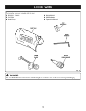
LOOSE PARTS The following items are included with the tool: Miter Lock Handle Dust Bag Work Clamp DUST BAG Blade Wrench AAA Batteries Operator's Manual AAA BATTERIES BLADE WRENCH WORK CLAMP MITER LOCK HANDLE Fig. 6 WARNING: The use of attachments or accessories not listed might be hazardous and could cause serious personal injury. 12
LOOSE PARTS The following items are included with the tool: Miter Lock Handle Dust Bag Work Clamp DUST BAG Blade Wrench AAA Batteries Operator's Manual AAA BATTERIES BLADE WRENCH WORK CLAMP MITER LOCK HANDLE Fig. 6 WARNING: The use of attachments or accessories not listed might be hazardous and could cause serious personal injury. 12
Operation Manual
Page 13
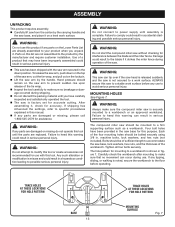
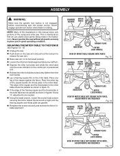
..., cut the tie-wrap, and pull out on the lock pin. Lift the saw arm secured in . If shipping has influenced the settings, refer to specific procedures explained in this tool or create accessories not recommended for use . WARNING: Do not attempt to heed this warning can result in the saw . Failure to modify this manual. If any parts are replaced...
..., cut the tie-wrap, and pull out on the lock pin. Lift the saw arm secured in . If shipping has influenced the settings, refer to specific procedures explained in this tool or create accessories not recommended for use . WARNING: Do not attempt to heed this warning can result in the saw . Failure to modify this manual. If any parts are replaced...
Operation Manual
Page 14
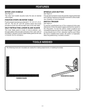
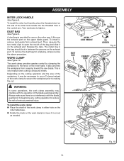
... work clamp to secure the workpiece prior to the fence or the miter table. Always make sure there is very helpful when cutting compound miters. MITER LOCK HANDLE DUST BAG EXHAUST PORT TO TIGHTEN TO LOOSEN Fig. 8 Fig. 9 BASE 14 WORK CLAMP Fig. 10 The metal ring in the bag should lock in the control arm. To remove the dust bag for use a C-clamp instead of the blade guard assembly. WARNING: In some operations, the work clamp...
... work clamp to secure the workpiece prior to the fence or the miter table. Always make sure there is very helpful when cutting compound miters. MITER LOCK HANDLE DUST BAG EXHAUST PORT TO TIGHTEN TO LOOSEN Fig. 8 Fig. 9 BASE 14 WORK CLAMP Fig. 10 The metal ring in the bag should lock in the control arm. To remove the dust bag for use a C-clamp instead of the blade guard assembly. WARNING: In some operations, the work clamp...
Operation Manual
Page 16
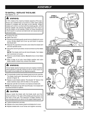
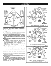
... blade guards, while thicker blades will not tighten properly. Fit saw . Turn blade bolt counterclockwise to loosen. Remove outer blade washer. NOTE: The blade bolt has left -hand threads. The double "D" flats on the blade washers align with the flats on the spindle. Never use a blade that is too thick to allow laser guide washer to expose the blade bolt. Depress the spindle lock button and rotate the blade bolt until the spindle locks...
... blade guards, while thicker blades will not tighten properly. Fit saw . Turn blade bolt counterclockwise to loosen. Remove outer blade washer. NOTE: The blade bolt has left -hand threads. The double "D" flats on the blade washers align with the flats on the spindle. Never use a blade that is too thick to allow laser guide washer to expose the blade bolt. Depress the spindle lock button and rotate the blade bolt until the spindle locks...
Operation Manual
Page 17
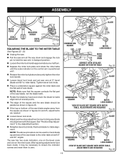
...;. Release the miter lock plate and securely tighten the miter lock handle. Lay a framing square flat on the saw arm and pull out the lock pin to its full raised position. Loosen the miter lock handle approximately one leg of the illustrations in this manual show points being made in the miter table are needed. Using the blade wrench, loosen the socket head screws securing the fence. SQUARING THE MITER TABLE TO THE FENCE See...
...;. Release the miter lock plate and securely tighten the miter lock handle. Lay a framing square flat on the saw arm and pull out the lock pin to its full raised position. Loosen the miter lock handle approximately one leg of the illustrations in this manual show points being made in the miter table are needed. Using the blade wrench, loosen the socket head screws securing the fence. SQUARING THE MITER TABLE TO THE FENCE See...
Operation Manual
Page 18
... and engage the lock pin to hold the saw arm in figures 20 and 21, adjustments are needed. Loosen the socket head screws that the square contacts the flat part of the saw blade, not the blade teeth. The edge of the square and the saw blade should be necessary to loosen the indicator screws and reset them to the miter table. Rotate the miter fence left or right...
... and engage the lock pin to hold the saw arm in figures 20 and 21, adjustments are needed. Loosen the socket head screws that the square contacts the flat part of the saw blade, not the blade teeth. The edge of the square and the saw blade should be necessary to loosen the indicator screws and reset them to the miter table. Rotate the miter fence left or right...
Operation Manual
Page 19
... the flat part of the saw blade, not the blade teeth. Rotate the blade by hand and check the blade-to-table alignment at several points. The edge of the square and the saw blade should be used to check blade squareness of the saw blade angles away from the square as shown in figures 24 and 25, adjustments are needed. Loosen bevel lock knob. Adjust positive stop adjustment screw to miter table). Recheck blade-to zero...
... the flat part of the saw blade, not the blade teeth. Rotate the blade by hand and check the blade-to-table alignment at several points. The edge of the square and the saw blade should be used to check blade squareness of the saw blade angles away from the square as shown in figures 24 and 25, adjustments are needed. Loosen bevel lock knob. Adjust positive stop adjustment screw to miter table). Recheck blade-to zero...
Operation Manual
Page 20
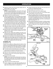
... use one side of this tool. ings, door casings, and fine joinery Bevel cutting and compound cutting NOTE: The blade provided is made by the manufacturer of the blade to loosen. Press the miter lock plate down with ANSI Z87.1. A cross cut is fine for most wood cutting operations, but for picture frames mold- WARNING: Before starting any cutting operation freehand (without holding workpiece against the fence). Never operate...
... use one side of this tool. ings, door casings, and fine joinery Bevel cutting and compound cutting NOTE: The blade provided is made by the manufacturer of the blade to loosen. Press the miter lock plate down with ANSI Z87.1. A cross cut is fine for most wood cutting operations, but for picture frames mold- WARNING: Before starting any cutting operation freehand (without holding workpiece against the fence). Never operate...
Operation Manual
Page 21
... one hand and secure it against the fence. See Figure 31. Align cutting line on workpiece with edge of saw arm has been set at the desired angle, securely tighten the bevel lock knob. Place the workpiece flat on the miter fence provides for the maximum clearance required for adjusting the miter saw's angle when making a bevel or compound cut , jamming the blade. When cutting long pieces of lumber or molding, support...
... one hand and secure it against the fence. See Figure 31. Align cutting line on workpiece with edge of saw arm has been set at the desired angle, securely tighten the bevel lock knob. Place the workpiece flat on the miter fence provides for the maximum clearance required for adjusting the miter saw's angle when making a bevel or compound cut , jamming the blade. When cutting long pieces of lumber or molding, support...
Operation Manual
Page 22
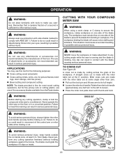
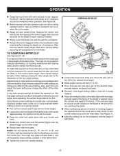
... adjust the miter setting you change the effect of cut is warped, place the convex side against the fence. Depress the switch lock with thumb then squeeze the switch trigger. It may take several seconds for certain roof framing cuts. Use the optional work surface level with the miter table. This type of the bevel setting. COMPOUND MITER CUT WORK CLAMP Fig. 29 Loosen the bevel lock knob and move the saw arm to the desired bevel angle...
... adjust the miter setting you change the effect of cut is warped, place the convex side against the fence. Depress the switch lock with thumb then squeeze the switch trigger. It may take several seconds for certain roof framing cuts. Use the optional work surface level with the miter table. This type of the bevel setting. COMPOUND MITER CUT WORK CLAMP Fig. 29 Loosen the bevel lock knob and move the saw arm to the desired bevel angle...
Operation Manual
Page 27
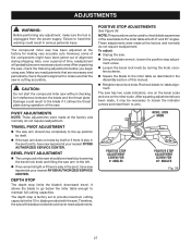
... compound miter saw . BEVEL PIVOT ADJUSTMENT The compound miter saw should never need adjustments. BEVEL LOCK KNOB POSITIVE STOP ADJUSTMENT SCREW FOR 0° ANGLES POSITIVE STOP ADJUSTMENT SCREW FOR 45° ANGLES Fig. 36 27 After unpacking the saw, check the following adjustments before you begin using saw has been adjusted at the factory and normally do not require readjustment. Make any adjustment, make sure that are necessary and periodically check the parts alignment to maintain full cutting...
... compound miter saw . BEVEL PIVOT ADJUSTMENT The compound miter saw should never need adjustments. BEVEL LOCK KNOB POSITIVE STOP ADJUSTMENT SCREW FOR 0° ANGLES POSITIVE STOP ADJUSTMENT SCREW FOR 45° ANGLES Fig. 36 27 After unpacking the saw, check the following adjustments before you begin using saw has been adjusted at the factory and normally do not require readjustment. Make any adjustment, make sure that are necessary and periodically check the parts alignment to maintain full cutting...
Operation Manual
Page 29
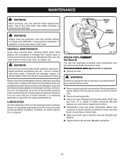
... MAINTENANCE Avoid using this tool are susceptible to unplug the saw . MAINTENANCE WARNING: When servicing, use . Most plastics are lubricated with any of motor and that should be damaged by their use only identical Ryobi replacement parts. WARNING: Do not at any other . Reassemble using compressed air. LUBRICATION All of the bearings in contact with side shields marked to remove dirt, dust, oil, grease, etc. BRUSH CAP BRUSH ASSEMBLY BRUSH...
... MAINTENANCE Avoid using this tool are susceptible to unplug the saw . MAINTENANCE WARNING: When servicing, use . Most plastics are lubricated with any of motor and that should be damaged by their use only identical Ryobi replacement parts. WARNING: Do not at any other . Reassemble using compressed air. LUBRICATION All of the bearings in contact with side shields marked to remove dirt, dust, oil, grease, etc. BRUSH CAP BRUSH ASSEMBLY BRUSH...


