Operation Manual
Page 1
... the model number above 265°F (130°C) may result in personal injury, fire, or damage. Do not charge battery in an area of electric shock. Do not use, store, or charge battery packs in use a clean cloth when cleaning. Failure to follow all instructions listed below, may cause sparks, burns, or a fire and can make a connection from oil and grease. OPERATOR'S MANUAL 40...
... the model number above 265°F (130°C) may result in personal injury, fire, or damage. Do not charge battery in an area of electric shock. Do not use, store, or charge battery packs in use a clean cloth when cleaning. Failure to follow all instructions listed below, may cause sparks, burns, or a fire and can make a connection from oil and grease. OPERATOR'S MANUAL 40...

Operation Manual
Page 2
... using a tool continuously, the battery pack may prohibit disposal of lithium-ion batteries in fire and/or serious injury. When the battery pack warms to charge. Upon removal, cover the battery pack's terminals with these batteries, especially when wearing rings and jewelry, could result in ordinary trash. BATTERY FUEL GAUGE To display the amount of charge left in the battery, press the charge level...
... using a tool continuously, the battery pack may prohibit disposal of lithium-ion batteries in fire and/or serious injury. When the battery pack warms to charge. Upon removal, cover the battery pack's terminals with these batteries, especially when wearing rings and jewelry, could result in ordinary trash. BATTERY FUEL GAUGE To display the amount of charge left in the battery, press the charge level...

Operation Manual 1
Page 2
... extension cord should not be used unless absolutely necessary. SAVE THESE INSTRUCTIONS - Before using battery charger, read all instructions listed below : Cord Length (Feet) 25' 50' 100' Cord Size (AWG) 16 16 16 NOTE: AWG = American Wire Gauge Do not operate charger with plastic parts. WARNING: Charge only one lithium-ion rechargeable battery at a time. Damage to the charger during a power surge. Risk of electric shock...
... extension cord should not be used unless absolutely necessary. SAVE THESE INSTRUCTIONS - Before using battery charger, read all instructions listed below : Cord Length (Feet) 25' 50' 100' Cord Size (AWG) 16 16 16 NOTE: AWG = American Wire Gauge Do not operate charger with plastic parts. WARNING: Charge only one lithium-ion rechargeable battery at a time. Damage to the charger during a power surge. Risk of electric shock...

Operation Manual 1
Page 3
...Direct Current Risk of injury, user must read and understand operator's manual before using this product. Proper interpretation of current ASSEMBLY WARNING: Do not use with damaged or missing parts could result in death or ...parts appear to modify this product if it is misuse and could result in damp locations. English Do not expose battery, battery compartment, or electronic components to a potential injury (e.g. Voltage Frequency (cycles per second) Power Type of current Type or a characteristic of these symbols will result in minor or moderate injury. Use...
...Direct Current Risk of injury, user must read and understand operator's manual before using this product. Proper interpretation of current ASSEMBLY WARNING: Do not use with damaged or missing parts could result in death or ...parts appear to modify this product if it is misuse and could result in damp locations. English Do not expose battery, battery compartment, or electronic components to a potential injury (e.g. Voltage Frequency (cycles per second) Power Type of current Type or a characteristic of these symbols will result in minor or moderate injury. Use...
Operation Manual 1
Page 4
... is 100% charged. To remove the battery pack from the power source. APPLICATIONS You may use . Battery packs are shipped in a dry location. NOTE: The connection between the battery pack and charger may be placed directly onto a hot battery pack but charging will become hot. See LED Functions for Battery Charging for electrical check. All battery pack LEDs will automatically begin...
... is 100% charged. To remove the battery pack from the power source. APPLICATIONS You may use . Battery packs are shipped in a dry location. NOTE: The connection between the battery pack and charger may be placed directly onto a hot battery pack but charging will become hot. See LED Functions for Battery Charging for electrical check. All battery pack LEDs will automatically begin...

Operation Manual 1
Page 5
... instructions). • If a different battery also indicates Error, the charger should be replaced. Charging Battery Pack Fast charging OFF Flashing OFF Battery is complete. *Charger LED will all turn off. OPERATION LED FUNCTIONS FOR BATTERY CHARGING See Figure 2, page 7. Battery Pack is Ready Battery full OFF ON* OFF Battery charging is being charged. ILLUSTRATIONS START ON PAGE 7. 5 - Error Error Flashing Flashing OFF Battery pack or charger error...
... instructions). • If a different battery also indicates Error, the charger should be replaced. Charging Battery Pack Fast charging OFF Flashing OFF Battery is complete. *Charger LED will all turn off. OPERATION LED FUNCTIONS FOR BATTERY CHARGING See Figure 2, page 7. Battery Pack is Ready Battery full OFF ON* OFF Battery charging is being charged. ILLUSTRATIONS START ON PAGE 7. 5 - Error Error Flashing Flashing OFF Battery pack or charger error...
Operation Manual
Page 4
... correct tool for lubrication and changing accessories. Keep firm footing and balance. Keep power head handles dry, clean, and free from cutting area. Make sure all parts of your lungs. READ ALL INSTRUCTIONS For safe operation, read and understand all safety instructions. A guard or other part that is dangerous and must be controlled with care - Use only manufacturer's recommended attachments. Maintain appliance with the switch trigger...
... correct tool for lubrication and changing accessories. Keep firm footing and balance. Keep power head handles dry, clean, and free from cutting area. Make sure all parts of your lungs. READ ALL INSTRUCTIONS For safe operation, read and understand all safety instructions. A guard or other part that is dangerous and must be controlled with care - Use only manufacturer's recommended attachments. Maintain appliance with the switch trigger...
Operation Manual
Page 5
... that the switch trigger is turned off when clearing jammed material. If liquid gets into an electrical outlet; Refer to them frequently and use them these instructions. Check with the string head located over 30 in the presence of a source of debris to avoid overheating the motor. Saw chain continues to explosion. IMPORTANT SAFETY INSTRUCTIONS Do not use any other brand of cutting head to the string trimmer attachment can...
... that the switch trigger is turned off when clearing jammed material. If liquid gets into an electrical outlet; Refer to them frequently and use them these instructions. Check with the string head located over 30 in the presence of a source of debris to avoid overheating the motor. Saw chain continues to explosion. IMPORTANT SAFETY INSTRUCTIONS Do not use any other brand of cutting head to the string trimmer attachment can...
Operation Manual
Page 6
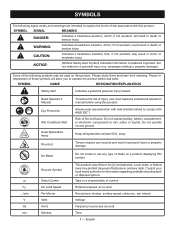
...user must read and understand operator's manual before using this product. Eye Protection Always wear eye protection with ANSI Z87.1. This product uses lithium-ion (Li-ion) batteries. Keep Bystanders Away Keep all bystanders at no .../min V Hz min No Blade Recycle Symbol Direct Current No Load Speed Per Minute Volts Hertz Minutes Do not install or use any type... the levels of fire and burns. Do not operate on wet ground. Ricochet Thrown objects can ricochet and result in death or serious injury. Type or a characteristic of current Rotational speed, at...
...user must read and understand operator's manual before using this product. Eye Protection Always wear eye protection with ANSI Z87.1. This product uses lithium-ion (Li-ion) batteries. Keep Bystanders Away Keep all bystanders at no .../min V Hz min No Blade Recycle Symbol Direct Current No Load Speed Per Minute Volts Hertz Minutes Do not install or use any type... the levels of fire and burns. Do not operate on wet ground. Ricochet Thrown objects can ricochet and result in death or serious injury. Type or a characteristic of current Rotational speed, at...

Operation Manual
Page 7
... each optional attachment used on the Packing List are attempting. WARNING: Do not use with brush cutters or other attachments could cause serious personal injury, always remove the battery pack from the box. Parts on the tool and in this power head and follow all operating features and safety rules. n If any accessories from the product when assembling parts. WARNING: If any parts on this operator's manual as...
... each optional attachment used on the Packing List are attempting. WARNING: Do not use with brush cutters or other attachments could cause serious personal injury, always remove the battery pack from the box. Parts on the tool and in this power head and follow all operating features and safety rules. n If any accessories from the product when assembling parts. WARNING: If any parts on this operator's manual as...
Operation Manual
Page 8
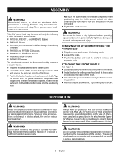
... operat- check it periodically for each optional attachment used and as prescribed in serious personal injury. 6 - ATTACHING THE FRONT HANDLE See Figure 3. Loosen and remove the wing nut and bolt from the handle. Install the handle on the power head shaft at the location indicated by means of a coupler device. Stop the motor and remove the battery pack. Loosen the knob on the shaft. Adjust handle up...
... operat- check it periodically for each optional attachment used and as prescribed in serious personal injury. 6 - ATTACHING THE FRONT HANDLE See Figure 3. Loosen and remove the wing nut and bolt from the handle. Install the handle on the power head shaft at the location indicated by means of a coupler device. Stop the motor and remove the battery pack. Loosen the knob on the shaft. Adjust handle up...

Operation Manual
Page 9
... power head away from your tool when you are replaced. Any contact with switch trigger completely depressed. WARNING: To avoid serious personal injury, always remove the battery pack and keep hands clear of a blade or any attachment could cause the battery pack to the Operator's Manuals for damaged, missing, or loose parts such as screws, nuts, bolts, caps, etc. OPERATION NOTICE: Before each use, inspect the entire product for your RYOBI battery...
... power head away from your tool when you are replaced. Any contact with switch trigger completely depressed. WARNING: To avoid serious personal injury, always remove the battery pack and keep hands clear of a blade or any attachment could cause the battery pack to the Operator's Manuals for damaged, missing, or loose parts such as screws, nuts, bolts, caps, etc. OPERATION NOTICE: Before each use, inspect the entire product for your RYOBI battery...
Operation Manual
Page 10
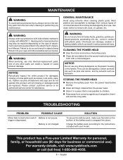
... replacement parts. CLEANING THE POWER HEAD Stop the motor and remove the battery pack. Clean dirt and debris from the power head before storing. Clean all missing or damaged parts are susceptible to remove dirt, dust, oil, grease, etc. STORING THE POWER HEAD Remove the battery pack from the power head using solvents when cleaning plastic parts. SOLUTION To secure the battery pack, make sure the latch on the type of attachment used and as screws, nuts, bolts, caps...
... replacement parts. CLEANING THE POWER HEAD Stop the motor and remove the battery pack. Clean dirt and debris from the power head before storing. Clean all missing or damaged parts are susceptible to remove dirt, dust, oil, grease, etc. STORING THE POWER HEAD Remove the battery pack from the power head using solvents when cleaning plastic parts. SOLUTION To secure the battery pack, make sure the latch on the type of attachment used and as screws, nuts, bolts, caps...
Parts Diagram
Page 3
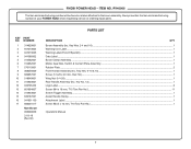
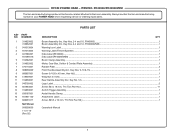
... manufacturing number of your POWER HEAD when requesting service or ordering repair parts. Key No. 12)...1 Logo Label...2 Screw (M4 x 18 mm, T15 Torx Pan Hd.)...11 Switch Trigger Assembly...1 Assist Handle Clamp...1 Attachment Label...1 Screw (M3.5 x 16 mm, T10 Torx Pan Hd.)...1 Operator's Manual 3 RYOBI POWER HEAD - ITEM NO. KEY PART NO. Key Nos. 2-4 and 16)...1 Warning Icon Label...1 Warning Label (French/Spanish)...1 Data Label...1 Boom Clamp Assembly...1 Motor, Gear Box, Switch...
... manufacturing number of your POWER HEAD when requesting service or ordering repair parts. Key No. 12)...1 Logo Label...2 Screw (M4 x 18 mm, T15 Torx Pan Hd.)...11 Switch Trigger Assembly...1 Assist Handle Clamp...1 Attachment Label...1 Screw (M3.5 x 16 mm, T10 Torx Pan Hd.)...1 Operator's Manual 3 RYOBI POWER HEAD - ITEM NO. KEY PART NO. Key Nos. 2-4 and 16)...1 Warning Icon Label...1 Warning Label (French/Spanish)...1 Data Label...1 Boom Clamp Assembly...1 Motor, Gear Box, Switch...

Parts Diagram
Page 4
RYOBI POWER HEAD - RY40006 CONTACT PLATE FUSE RED RED BLACK MOTOR RED SWITCH BLACK WIRING DIAGRAM 4 BLACK ITEM NO.
RYOBI POWER HEAD - RY40006 CONTACT PLATE FUSE RED RED BLACK MOTOR RED SWITCH BLACK WIRING DIAGRAM 4 BLACK ITEM NO.
Parts Diagram 1
Page 3
RYOBI POWER HEAD - Key No. 12)...1 Logo Label...2 Screw (M4 x 18 mm, T15 Torx Pan Hd.)...11 Switch Trigger Assembly...1 Assist Handle Clamp...1 Attachment Label...1 Screw (M3.5 x 16 mm, T10 Torx Pan Hd.)...1 Operator's Manual 3 RY40006/RY40006VNM The item and manufacturing number will be found on a label attached to the boom assembly. Key Nos. 9-10 & 15)...1 Screw (1/4-20 x 40 mm, Hex Hd.)...1 Wing Nut (1/4-20)...1 Rear Handle Assembly (Inc. ITEM...
RYOBI POWER HEAD - Key No. 12)...1 Logo Label...2 Screw (M4 x 18 mm, T15 Torx Pan Hd.)...11 Switch Trigger Assembly...1 Assist Handle Clamp...1 Attachment Label...1 Screw (M3.5 x 16 mm, T10 Torx Pan Hd.)...1 Operator's Manual 3 RY40006/RY40006VNM The item and manufacturing number will be found on a label attached to the boom assembly. Key Nos. 9-10 & 15)...1 Screw (1/4-20 x 40 mm, Hex Hd.)...1 Wing Nut (1/4-20)...1 Rear Handle Assembly (Inc. ITEM...

Parts Diagram 1
Page 4
RY40006/RY40006VNM CONTACT PLATE RED FUSE RED MOTOR RED BLACK SWITCH WIRING DIAGRAM 4 BLACK ITEM NO. RYOBI POWER HEAD -
RY40006/RY40006VNM CONTACT PLATE RED FUSE RED MOTOR RED BLACK SWITCH WIRING DIAGRAM 4 BLACK ITEM NO. RYOBI POWER HEAD -


