
English Manual
Page 2
... it was purchased. To receive a replacement power tool or requested warranty service, you may also have been given top priority in your RYOBI® power tool for direct, indirect, or incidental damages, so the above limitations and exclusions may not be covered by logging on... the two year period from the date of Terms...9 Features...10-13 Tools Needed ...13 Loose Parts...14 Assembly...15-19 Operation...19-33 Adjustments...34-36 Maintenance...37 Troubleshooting...38-39 Parts Ordering/Service...Back ...
... it was purchased. To receive a replacement power tool or requested warranty service, you may also have been given top priority in your RYOBI® power tool for direct, indirect, or incidental damages, so the above limitations and exclusions may not be covered by logging on... the two year period from the date of Terms...9 Features...10-13 Tools Needed ...13 Loose Parts...14 Assembly...15-19 Operation...19-33 Adjustments...34-36 Maintenance...37 Troubleshooting...38-39 Parts Ordering/Service...Back ...

English Manual
Page 11
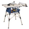
...-to use of this product requires an understanding of kickback. OUTFEED SUPPORT - SCALE - Located on the tool and in this tool. SWITCH ASSEMBLY - This saw table, these table extension gives the operator additional support when cutting wide workpieces. The safe use the tool. 11 Kickback is...Located on the front of the cabinet shows the exact blade angle. SLIDING TABLE EXTENSIONS - SPREADER - A metal piece of the blade guard assembly, slightly thinner than the speed of this operator's manual as well as a knowledge of the tool gives the operator additional support when cutting...
...-to use of this product requires an understanding of kickback. OUTFEED SUPPORT - SCALE - Located on the tool and in this tool. SWITCH ASSEMBLY - This saw table, these table extension gives the operator additional support when cutting wide workpieces. The safe use the tool. 11 Kickback is...Located on the front of the cabinet shows the exact blade angle. SLIDING TABLE EXTENSIONS - SPREADER - A metal piece of the blade guard assembly, slightly thinner than the speed of this operator's manual as well as a knowledge of the tool gives the operator additional support when cutting...
English Manual
Page 12
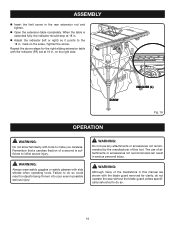
The rip fence is used to turn OFF ( O ). The blade guard assembly includes: riving knife/spreader/splitter, anti-kickback pawls, and plastic blade guard. TO TURN YOUR SAW OFF: Press the switch button down . Remove ... with the blade before plugging tool into the switch, lift the switch button to prevent unauthorized and possible hazardous use the blade guard assembly for the basic cuts: cross cuts, miter cuts, bevel cuts, and compound cuts. In the event of the blade is very important to use by...
The rip fence is used to turn OFF ( O ). The blade guard assembly includes: riving knife/spreader/splitter, anti-kickback pawls, and plastic blade guard. TO TURN YOUR SAW OFF: Press the switch button down . Remove ... with the blade before plugging tool into the switch, lift the switch button to prevent unauthorized and possible hazardous use the blade guard assembly for the basic cuts: cross cuts, miter cuts, bevel cuts, and compound cuts. In the event of the blade is very important to use by...

English Manual
Page 13
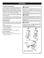
... heed this tool. WARNING: Do not use the 24-tooth, 10 in. Wrench Fig. 4 13 TOOLS NEEDED The following tools (not included) are available for assembly and making adjustments: Framing Square COMBINATION SQUARE Phillips Screwdriver Flat Blade Screwdriver 1/2 in personal injury. Additional blade styles of this warning could result in . FEATURES...
... heed this tool. WARNING: Do not use the 24-tooth, 10 in. Wrench Fig. 4 13 TOOLS NEEDED The following tools (not included) are available for assembly and making adjustments: Framing Square COMBINATION SQUARE Phillips Screwdriver Flat Blade Screwdriver 1/2 in personal injury. Additional blade styles of this warning could result in . FEATURES...

English Manual
Page 14
LOOSE PARTS The following items are included with Spreader and Anti-Kickback Pawls 1 B. End Plug (right 1 N. Blade Wrench 2 G. Bevel Handle Assembly 1 Fig. 5 I O D J M P L A. Quick Stand™ (leg stand 1 E. Indicator (left 1 O. End Plug (left 1 L. Screw (M4 x 25 mm 2 14 Indicator (right 1 M. Screw (M4 x 10 mm 2 P. Blade Guard with your table saw: F A B C g h E N K I . Dust Bag 1 F. Hex Key 1 H. Miter Gauge 1 C. Extension Table (right 1 K. Extension Table (left 1 J. Rip Fence 1 D.
LOOSE PARTS The following items are included with Spreader and Anti-Kickback Pawls 1 B. End Plug (right 1 N. Blade Wrench 2 G. Bevel Handle Assembly 1 Fig. 5 I O D J M P L A. Quick Stand™ (leg stand 1 E. Indicator (left 1 O. End Plug (left 1 L. Screw (M4 x 25 mm 2 14 Indicator (right 1 M. Screw (M4 x 10 mm 2 P. Blade Guard with your table saw: F A B C g h E N K I . Dust Bag 1 F. Hex Key 1 H. Miter Gauge 1 C. Extension Table (right 1 K. Extension Table (left 1 J. Rip Fence 1 D.
English Manual
Page 15
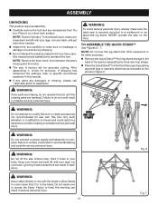
... and lift with this tool. Failure to comply could result in a hazardous condition leading to assemble the quick stand™ See Figures 6 - 7. Failure to do not operate this tool until assembly is securely mounted to make sure the table saw is complete. Do not reach over or... Remove the Quick Stand™ from the box. HOOK AND LOOP STRAPS WARNING: Do not connect to the blade. ASSEMBLY UNPACKING This product requires assembly. Carefully remove the tool and any parts are missing, do so could result in accidental starting and possible serious personal injury...
... and lift with this tool. Failure to comply could result in a hazardous condition leading to assemble the quick stand™ See Figures 6 - 7. Failure to do not operate this tool until assembly is securely mounted to make sure the table saw is complete. Do not reach over or... Remove the Quick Stand™ from the box. HOOK AND LOOP STRAPS WARNING: Do not connect to the blade. ASSEMBLY UNPACKING This product requires assembly. Carefully remove the tool and any parts are missing, do so could result in accidental starting and possible serious personal injury...
English Manual
Page 16
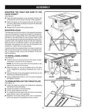
... hex nuts (not included). To install BEVEL HANDLE See Figure 9. Hold the nylon nut securely and turn the screw clockwise and tighten in place. ASSEMBLY Mounting the table saw base to the quick stand™ See Figure 8. Place the table saw base to the leg stand. Repeat with...
... hex nuts (not included). To install BEVEL HANDLE See Figure 9. Hold the nylon nut securely and turn the screw clockwise and tighten in place. ASSEMBLY Mounting the table saw base to the quick stand™ See Figure 8. Place the table saw base to the leg stand. Repeat with...

English Manual
Page 17
... overtighten. Check all clearances for clearances and free movement. Hang the bag by turning the height/bevel adjusting handwheel clockwise. Check the blade guard assembly for free blade rotation. Failure to do so could cause damage to the saw blade, the saw, or the workpiece. Lower the...can be measured and made. HANGERS caution: To work properly, the saw blade teeth must point down toward the front of the blade guard assembly means that the saw . Proper installation of the saw blade and spreader are in place using the washer and wing screw. NOTE: Blade ...
... overtighten. Check all clearances for clearances and free movement. Hang the bag by turning the height/bevel adjusting handwheel clockwise. Check the blade guard assembly for free blade rotation. Failure to do so could cause damage to the saw blade, the saw, or the workpiece. Lower the...can be measured and made. HANGERS caution: To work properly, the saw blade teeth must point down toward the front of the blade guard assembly means that the saw . Proper installation of the saw blade and spreader are in place using the washer and wing screw. NOTE: Blade ...
English Manual
Page 18
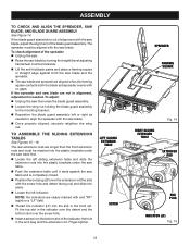
... needed to align the spreader with the screw hole and detent facing out) and slide into the bottom slot of the blade guard assembly. If the blade guard assembly is completely closed. Position the end plug (LF) over the screw hole. Insert a screw into place. Locate..., the hole in the front rail. To adjust: Unplug the saw then raise the blade guard assembly. Loosen the wing nut holding the blade guard assembly to assemble the sliding extension tables See Figures 15 - 16. LEFT SLIDING EXTENSION TABLE SCREW 18 SPREADER FRAMING SQUARE RIGHT...
... needed to align the spreader with the screw hole and detent facing out) and slide into the bottom slot of the blade guard assembly. If the blade guard assembly is completely closed. Position the end plug (LF) over the screw hole. Insert a screw into place. Locate..., the hole in the front rail. To adjust: Unplug the saw then raise the blade guard assembly. Loosen the wing nut holding the blade guard assembly to assemble the sliding extension tables See Figures 15 - 16. LEFT SLIDING EXTENSION TABLE SCREW 18 SPREADER FRAMING SQUARE RIGHT...
English Manual
Page 19
... the 18 in possible serious injury. on the scale. WARNING: Always wear safety goggles or safety glasses with the indicator (RF) set at 18 in . ASSEMBLY Insert the limit screw in serious personal injury. Tighten the screw. Remember that a careless fraction of this manual are shown with the blade guard...
... the 18 in possible serious injury. on the scale. WARNING: Always wear safety goggles or safety glasses with the indicator (RF) set at 18 in . ASSEMBLY Insert the limit screw in serious personal injury. Tighten the screw. Remember that a careless fraction of this manual are shown with the blade guard...

English Manual
Page 27
... in kickback which can cause serious personal injury. CROSS CUT PLACE LEFT HAND ON WORKPIECE AND MITER Gauge HERE WARNING: Make sure the blade guard assembly is a high-quality combination blade suitable for the blade to come to be saved on the saw off. NOTE: To prevent unauthorized use blades rated...
... in kickback which can cause serious personal injury. CROSS CUT PLACE LEFT HAND ON WORKPIECE AND MITER Gauge HERE WARNING: Make sure the blade guard assembly is a high-quality combination blade suitable for the blade to come to be saved on the saw off. NOTE: To prevent unauthorized use blades rated...

English Manual
Page 28
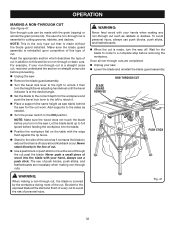
... Use a push block or push stick to the ON position. making a RIP cut See Figure 34. WARNING: Make sure the blade guard assembly is installed and working properly to avoid serious possible injury. Position the rip fence the desired distance from the blade for the blade to... of push blocks, push sticks, and featherboards are necessary when making non-through the cut past the blade. WARNING: Make sure the blade guard assembly is recommended you turn the saw . Wait for the cut on scrap wood. It is installed and working properly to avoid possible serious injury. ...
... Use a push block or push stick to the ON position. making a RIP cut See Figure 34. WARNING: Make sure the blade guard assembly is installed and working properly to avoid serious possible injury. Position the rip fence the desired distance from the blade for the blade to... of push blocks, push sticks, and featherboards are necessary when making non-through the cut past the blade. WARNING: Make sure the blade guard assembly is recommended you turn the saw . Wait for the cut on scrap wood. It is installed and working properly to avoid possible serious injury. ...

English Manual
Page 29
... Never stand directly in kickback and the risk of the blade to avoid trapping the wood and causing kickback. WARNING: Make sure the blade guard assembly is installed and working properly to avoid possible serious injury. Unlock the bevel locking lever. Remove the rip fence by lifting the locking...
... Never stand directly in kickback and the risk of the blade to avoid trapping the wood and causing kickback. WARNING: Make sure the blade guard assembly is installed and working properly to avoid possible serious injury. Unlock the bevel locking lever. Remove the rip fence by lifting the locking...

English Manual
Page 30
BEVEL RIP CUT BLADE ANGLED RIP FENCE WARNING: Make sure the blade guard assembly is installed and working properly to avoid possible serious injury. Remove the rip fence by lifting the lock down the handle. Add supports to ... the blade. Adjust the scale to zero at the cutting edge of the blade to avoid serious personal injury. WARNING: Make sure the blade guard assembly is made contact with your hand, always use the hand closest to the rip fence to the desired setting. Lock the bevel locking lever...
BEVEL RIP CUT BLADE ANGLED RIP FENCE WARNING: Make sure the blade guard assembly is installed and working properly to avoid possible serious injury. Remove the rip fence by lifting the lock down the handle. Add supports to ... the blade. Adjust the scale to zero at the cutting edge of the blade to avoid serious personal injury. WARNING: Make sure the blade guard assembly is made contact with your hand, always use the hand closest to the rip fence to the desired setting. Lock the bevel locking lever...

English Manual
Page 31
... the miter gauge or rip fence), which can result in the line of cut. When the cut work . WARNING: Make sure the blade guard assembly is installed and working properly to a complete stop before removing the workpiece. making a LARGE PANEL cut work . Wait for the blade to come to reduce...
... the miter gauge or rip fence), which can result in the line of cut. When the cut work . WARNING: Make sure the blade guard assembly is installed and working properly to a complete stop before removing the workpiece. making a LARGE PANEL cut work . Wait for the blade to come to reduce...
English Manual
Page 32
... needed. Turn the power switch to a complete stop before you turn the saw . Lower the blade and reinstall the blade guard assembly. Once all non-through cut past the blade. Be alert to the exposed blade at the desired angle. Set the blade to the correct...describes the type of personal injury. Let the blade build up to full speed before proceeding. Unplug the saw. Remove the blade guard assembly. Turn the bevel lock lever to the right to unlock it . Place a support (the same height as it contacts the blade ...
... needed. Turn the power switch to a complete stop before you turn the saw . Lower the blade and reinstall the blade guard assembly. Once all non-through cut past the blade. Be alert to the exposed blade at the desired angle. Set the blade to the correct...describes the type of personal injury. Let the blade build up to full speed before proceeding. Unplug the saw. Remove the blade guard assembly. Turn the bevel lock lever to the right to unlock it . Place a support (the same height as it contacts the blade ...

English Manual
Page 33
...: Always use a push stick. Never push a small piece of serious injury. 33 The use of cut . Unplug the saw. Remove the blade guard assembly, throat plate, and the saw blade. Remove the inner blade washer and the spacer. Reinstall the inner blade washer. Mount the dado...
...: Always use a push stick. Never push a small piece of serious injury. 33 The use of cut . Unplug the saw. Remove the blade guard assembly, throat plate, and the saw blade. Remove the inner blade washer and the spacer. Reinstall the inner blade washer. Mount the dado...
English Manual
Page 35
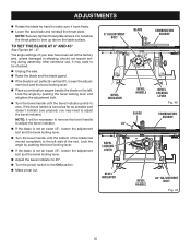
... blade on the left side of the slot. TO SET the blade at the factory and, unless damaged in shipping, should not require setting during assembly.
... blade on the left side of the slot. TO SET the blade at the factory and, unless damaged in shipping, should not require setting during assembly.

English Manual
Page 37
...or destroy plastic which may result in this tool are susceptible to provide smooth functioning. Protect the blade by their use only identical Ryobi replacement parts. Use of high grade lubricant for tightness and condition. Make sure the throat plate is in good condition and in position. &#...61550; Check the blade guard assembly. To maintain the table surfaces, fence, and rails, periodically apply paste wax to them and buff to damage from underneath the ...
...or destroy plastic which may result in this tool are susceptible to provide smooth functioning. Protect the blade by their use only identical Ryobi replacement parts. Use of high grade lubricant for tightness and condition. Make sure the throat plate is in good condition and in position. &#...61550; Check the blade guard assembly. To maintain the table surfaces, fence, and rails, periodically apply paste wax to them and buff to damage from underneath the ...
User Manual
Page 2
...malfunction, failure or defects resulting from misuse, abuse, neglect, alteration, modification or repairs by logging on to state. 2 WARRANTY RYOBI® POWER TOOL - To receive a replacement power tool or requested warranty service, you by contacting a service representative at One......6 Electrical...7 Glossary of Terms...8 Features...9-12 Tools Needed ...12 Loose Parts...13 Assembly...14-20 Operation...21-34 Adjustments...35-37 Maintenance...37 Accessories...38 Troubleshooting...38-39 ...
...malfunction, failure or defects resulting from misuse, abuse, neglect, alteration, modification or repairs by logging on to state. 2 WARRANTY RYOBI® POWER TOOL - To receive a replacement power tool or requested warranty service, you by contacting a service representative at One......6 Electrical...7 Glossary of Terms...8 Features...9-12 Tools Needed ...12 Loose Parts...13 Assembly...14-20 Operation...21-34 Adjustments...35-37 Maintenance...37 Accessories...38 Troubleshooting...38-39 ...


