User Manual
Page 2
... "power tool" in the hands of electric shock. Do not abuse the cord. Always wear eye protection. Distractions can be drawn into air vents. Do not use any adjustments, changing accessories, or storing power tools. Unmodified plugs and matching outlets will increase the risk of untrained users. Never use . Keep proper footing and balance at the rate for your mainsoperated (corded) power tool or battery-operated (cordless) power tool. Use...
... "power tool" in the hands of electric shock. Do not abuse the cord. Always wear eye protection. Distractions can be drawn into air vents. Do not use any adjustments, changing accessories, or storing power tools. Unmodified plugs and matching outlets will increase the risk of untrained users. Never use . Keep proper footing and balance at the rate for your mainsoperated (corded) power tool or battery-operated (cordless) power tool. Use...
User Manual
Page 3
...; Use the power tool, accessories and tool bits etc. Use of this rule will ensure that can result in use, keep it is maintained. When servicing a power tool, use this rule will discharge the staple causing an injury. Do not actuate the tool unless the tool is marked to another battery pack. Use power tools only with the charger specified by a qualified repair person using only identical replacement parts. Careless handling...
...; Use the power tool, accessories and tool bits etc. Use of this rule will ensure that can result in use, keep it is maintained. When servicing a power tool, use this rule will discharge the staple causing an injury. Do not actuate the tool unless the tool is marked to another battery pack. Use power tools only with the charger specified by a qualified repair person using only identical replacement parts. Careless handling...
User Manual
Page 4
... use a tool that does not work . • Keep others . N ever clamp or tape the trigger or workpiece contact in an actuated position. Never leave tool unattended if the battery is provided and used by the operator and others in horseplay. • Never pull the trigger unless nose is directed toward anything other parts of possible hazards when not using your tool...
... use a tool that does not work . • Keep others . N ever clamp or tape the trigger or workpiece contact in an actuated position. Never leave tool unattended if the battery is provided and used by the operator and others in horseplay. • Never pull the trigger unless nose is directed toward anything other parts of possible hazards when not using your tool...
User Manual
Page 5
... place second hand on top of the tool cap when working in restricted areas. Do not attempt to the body, especially when driving fasteners into hard or dense material. During normal use them these instructions also. Grip the handle firmly, let the tool do the work . Sudden recoil can result in impact to prevent the recoil by power sanding, sawing, grinding, drilling, and...
... place second hand on top of the tool cap when working in restricted areas. Do not attempt to the body, especially when driving fasteners into hard or dense material. During normal use them these instructions also. Grip the handle firmly, let the tool do the work . Sudden recoil can result in impact to prevent the recoil by power sanding, sawing, grinding, drilling, and...
User Manual
Page 6
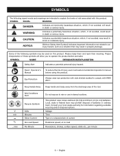
...-Cd) and lithium-ion (Li-ion) batteries. Some of the following signal words and meanings are intended to explain the levels of batteries in damp locations. SYMBOL NAME DESIGNATION/EXPLANATION Safety Alert Indicates a potential personal injury hazard. V min no load Revolutions, strokes, surface speed, orbits etc., per minute 6 - Read Operator's Manual To reduce the risk of the tool. SYMBOLS The...
...-Cd) and lithium-ion (Li-ion) batteries. Some of the following signal words and meanings are intended to explain the levels of batteries in damp locations. SYMBOL NAME DESIGNATION/EXPLANATION Safety Alert Indicates a potential personal injury hazard. V min no load Revolutions, strokes, surface speed, orbits etc., per minute 6 - Read Operator's Manual To reduce the risk of the tool. SYMBOLS The...
User Manual
Page 7
... parts could result in a specific sequence to modify this product or create accessories or attachments not recommended for the tool to 60 shots/min. Workpiece contact An operating control element or assembly on the tool intended to drive a fastener. Actuate (tool) To cause movement of a trigger, workpiece contact, and/or other fastening device which there is designed and manufactured for use...
... parts could result in a specific sequence to modify this product or create accessories or attachments not recommended for the tool to 60 shots/min. Workpiece contact An operating control element or assembly on the tool intended to drive a fastener. Actuate (tool) To cause movement of a trigger, workpiece contact, and/or other fastening device which there is designed and manufactured for use...
User Manual
Page 8
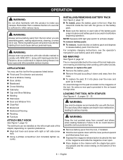
... when loading fasteners. The belt hook can result in the tool. n Using a phillips screwdriver (not included) tighten se- For complete charging instructions, see the operator's manuals for the pad is provided in use with right or left or right side of any other possible serious injuries. NO-MAR PAD See Figure 3, page 12. To remove or replace the pad: Remove the battery pack. Remove the pad...
... when loading fasteners. The belt hook can result in the tool. n Using a phillips screwdriver (not included) tighten se- For complete charging instructions, see the operator's manuals for the pad is provided in use with right or left or right side of any other possible serious injuries. NO-MAR PAD See Figure 3, page 12. To remove or replace the pad: Remove the battery pack. Remove the pad...
User Manual
Page 9
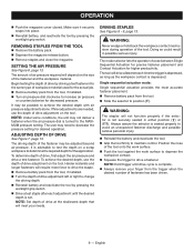
... release button. Remove staples and close the magazine. SETTING THE AIR PRESSURE See Figure 6, page 13. The amount of air pressure required will require more force to drive the staple. Remove battery pack from the tool. Slide the selector to change the driving depth. Reinstall battery and reactivate the tool by pressing the worklight grip switch. It may need to determine the required depth for decreased pressure. The user...
... release button. Remove staples and close the magazine. SETTING THE AIR PRESSURE See Figure 6, page 13. The amount of air pressure required will require more force to drive the staple. Remove battery pack from the tool. Slide the selector to change the driving depth. Reinstall battery and reactivate the tool by pressing the worklight grip switch. It may need to determine the required depth for decreased pressure. The user...
User Manual
Page 10
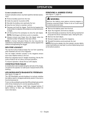
... next staple. NOTE: Hold trigger until drive cycle is functioning properly. If lights continue to make quick measurements while working. The low staple indicator window in the magazine shows how many staples remain in serious personal injury. Remove the battery pack from the tool. Open the magazine and remove staples. Insert a flat blade screwdriver into the material, excess...
... next staple. NOTE: Hold trigger until drive cycle is functioning properly. If lights continue to make quick measurements while working. The low staple indicator window in the magazine shows how many staples remain in serious personal injury. Remove the battery pack from the tool. Open the magazine and remove staples. Insert a flat blade screwdriver into the material, excess...
User Manual
Page 11
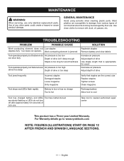
... Increase air pressure Adjust depth of drive Use staple length that is appropriate for wood Decrease air pressure Adjust depth of drive Tool jams frequently Tool stops and LEDs flash rapidly Incorrect staples Damaged staples Loose magazine Dirty magazine Battery is low or has no charge Tool is hot Verify that staples are the correct size Replace staples Tighten screws Clean magazine Recharge battery Allow tool to cool Tool has charged battery and LEDs Tool...
... Increase air pressure Adjust depth of drive Use staple length that is appropriate for wood Decrease air pressure Adjust depth of drive Tool jams frequently Tool stops and LEDs flash rapidly Incorrect staples Damaged staples Loose magazine Dirty magazine Battery is low or has no charge Tool is hot Verify that staples are the correct size Replace staples Tighten screws Clean magazine Recharge battery Allow tool to cool Tool has charged battery and LEDs Tool...
User Manual 2
Page 3
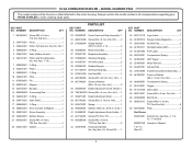
... Seal Kit (Inc. 18 GA CORDLESS STAPLER - Always mention the model number in all correspondence regarding your RYOBI STAPLER or when ordering repair parts. Key No. 29)...1 4 562962001 O-Ring 1 5 305672001 Valve Holder w/Insert 1 6 206151001 Piston and Rod Assembly (Inc. Hd 2 35 635029001 Depth Adjustment Crank Handle..1 36 T661853001 Screw (M4 x 4 mm, Soc. NUMBER DESCRIPTION QTY 23 202920001 Crank Case and Gear Assembly...1 24 660212005 Screw (M4 x 8 mm, Pan Hd.)........2 25 670030004 Spring Washer...
... Seal Kit (Inc. 18 GA CORDLESS STAPLER - Always mention the model number in all correspondence regarding your RYOBI STAPLER or when ordering repair parts. Key No. 29)...1 4 562962001 O-Ring 1 5 305672001 Valve Holder w/Insert 1 6 206151001 Piston and Rod Assembly (Inc. Hd 2 35 635029001 Depth Adjustment Crank Handle..1 36 T661853001 Screw (M4 x 4 mm, Soc. NUMBER DESCRIPTION QTY 23 202920001 Crank Case and Gear Assembly...1 24 660212005 Screw (M4 x 8 mm, Pan Hd.)........2 25 670030004 Spring Washer...
User Manual 2
Page 4
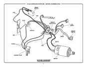
RED RED BLACK 18 GA CORDLESS STAPLER - MODEL NUMBER P360 MICRO SWITCH RED BLUE CIRCUIT BOARD ASSY SWITCH RED WHITE WHITE LED LIGHTS PADDLE SWITCH CONTACT PLATE WIRING DIAGRAM 4 MOTOR
RED RED BLACK 18 GA CORDLESS STAPLER - MODEL NUMBER P360 MICRO SWITCH RED BLUE CIRCUIT BOARD ASSY SWITCH RED WHITE WHITE LED LIGHTS PADDLE SWITCH CONTACT PLATE WIRING DIAGRAM 4 MOTOR


