Operation Manual
Page 2
.... Always wear eye protection. Stable footing on a ladder or unstable support. Save all safety warnings, instructions, illustrations and specifications provided with this product only with sharp cutting edges are less likely to a rotating part of electric shock. When operating a power tool outdoors, use an extension cord suitable for outdoor use reduces the risk of a second. Do not wear loose clothing or jewelry...
.... Always wear eye protection. Stable footing on a ladder or unstable support. Save all safety warnings, instructions, illustrations and specifications provided with this product only with sharp cutting edges are less likely to a rotating part of electric shock. When operating a power tool outdoors, use an extension cord suitable for outdoor use reduces the risk of a second. Do not wear loose clothing or jewelry...
Operation Manual
Page 3
... or excessive temperature. Service of the power tool "live " wire may exhibit unpredictable behavior resulting in accordance with specifically designated battery packs. Careless handling of the nailer can make exposed metal parts of battery packs should ALWAYS be performed. Unexpected triggering will ensure that the safety of the power tool is required to free a jammed condition. Do not use this nailer for electric cable installation and may damage...
... or excessive temperature. Service of the power tool "live " wire may exhibit unpredictable behavior resulting in accordance with specifically designated battery packs. Careless handling of the nailer can make exposed metal parts of battery packs should ALWAYS be performed. Unexpected triggering will ensure that the safety of the power tool is required to free a jammed condition. Do not use this nailer for electric cable installation and may damage...
Operation Manual
Page 4
... place holding the trigger. Accidental discharge could result. Always handle the tool with ANSI Z87.1. Additional safety protection will reduce the risk of electric shock, fire, or serious personal injury. Do not place battery tools or their use eye protection which can cause injury to clean your battery tool or when changing accessories. Do not put hands, head, or other than...
... place holding the trigger. Accidental discharge could result. Always handle the tool with ANSI Z87.1. Additional safety protection will reduce the risk of electric shock, fire, or serious personal injury. Do not place battery tools or their use eye protection which can cause injury to clean your battery tool or when changing accessories. Do not put hands, head, or other than...
Operation Manual
Page 5
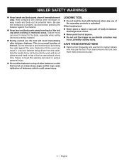
NAILER SAFETY WARNINGS Keep hands and body parts clear of tool. Never point tool at anyone. Do not pull the trigger as this may cause deflection of the tool cap when working in restricted areas. When loading tool: Never place a hand or any part of body in impact to them frequently and use them these instructions also. 5 - English This is a normal function...
NAILER SAFETY WARNINGS Keep hands and body parts clear of tool. Never point tool at anyone. Do not pull the trigger as this may cause deflection of the tool cap when working in restricted areas. When loading tool: Never place a hand or any part of body in impact to them frequently and use them these instructions also. 5 - English This is a normal function...
Operation Manual
Page 6
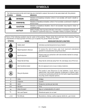
...Operator's Manual To reduce the risk of injury, user must read and understand operator's manual before using this product. Wet Conditions Alert Recycle Symbols V A Hz min no load Revolutions, strokes, surface speed, orbits etc., per minute 6 - Voltage Current Frequency (cycles per second) Time Type or a characteristic of current Rotational speed, at no .../min Volts Amperes Hertz Minutes Direct Current No Load Speed...may prohibit disposal of batteries in minor or moderate injury. Keep Hands Away Keep hands and body away from the discharge area of the tool. Some of the ...
...Operator's Manual To reduce the risk of injury, user must read and understand operator's manual before using this product. Wet Conditions Alert Recycle Symbols V A Hz min no load Revolutions, strokes, surface speed, orbits etc., per minute 6 - Voltage Current Frequency (cycles per second) Time Type or a characteristic of current Rotational speed, at no .../min Volts Amperes Hertz Minutes Direct Current No Load Speed...may prohibit disposal of batteries in minor or moderate injury. Keep Hands Away Keep hands and body away from the discharge area of the tool. Some of the ...

Operation Manual
Page 7
... which is in a position that allows the tool to be actuated or that satisifes one requirement for the tool to be pulled in a specific sequence in . FEATURES PRODUCT SPECIFICATIONS Magazine Capacity 130 fasteners Nail Type 23 gauge Headless Pin Nail Length 1/2 - 1-3/8 in order to drive a fastener. Trigger A tool operating control activated by a tool. Fastener A staple, pin, brad, nail, or other fastening device which there are damaged...
... which is in a position that allows the tool to be actuated or that satisifes one requirement for the tool to be pulled in a specific sequence in . FEATURES PRODUCT SPECIFICATIONS Magazine Capacity 130 fasteners Nail Type 23 gauge Headless Pin Nail Length 1/2 - 1-3/8 in order to drive a fastener. Trigger A tool operating control activated by a tool. Fastener A staple, pin, brad, nail, or other fastening device which there are damaged...
Operation Manual
Page 8
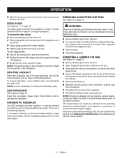
... drive a fastener. 8 - To replace the pad, fit it into your battery pack and charger. An extra no -mar pad attached to the nose of the tool. Failure to maintain control. Press the nose of the triggers are assembling parts, making adjustments, cleaning, or when not in possible serious injury. DRIVING PIN NAILS See Figure 6, page 12. The secondary trigger must be installed on operator preference. Removing battery...
... drive a fastener. 8 - To replace the pad, fit it into your battery pack and charger. An extra no -mar pad attached to the nose of the tool. Failure to maintain control. Press the nose of the triggers are assembling parts, making adjustments, cleaning, or when not in possible serious injury. DRIVING PIN NAILS See Figure 6, page 12. The secondary trigger must be installed on operator preference. Removing battery...
Operation Manual
Page 9
... See Figure 9, page 12. OPERATION Allow the tool to recoil away from the work surface as shown. Adjust edge guide to the width needed. Tighten edge guide lock knob securely. If worklight is driven. NOTE: The guiding edge of this manual. 9 - REMOVING A JAMMED PIN NAIL See Figure 11, page 12. Remove battery pack from the tool. Open magazine and remove nails from the tool, depress the maga- Failure...
... See Figure 9, page 12. OPERATION Allow the tool to recoil away from the work surface as shown. Adjust edge guide to the width needed. Tighten edge guide lock knob securely. If worklight is driven. NOTE: The guiding edge of this manual. 9 - REMOVING A JAMMED PIN NAIL See Figure 11, page 12. Remove battery pack from the tool. Open magazine and remove nails from the tool, depress the maga- Failure...
Operation Manual
Page 10
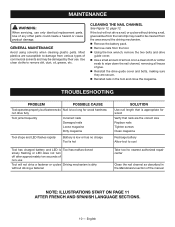
... the correct size Replace nails Tighten screws Clean magazine Recharge battery Allow tool to cool Take tool to nearest authorized repair center Clean the nail channel as described in the tool and close the magazine. MAINTENANCE WARNING: When servicing, use . If the tool will not drive a nail, or cycles without driving a fastener SOLUTION Use nail length that nails are susceptible to remove dirt, dust, oil, grease, etc. Use of glue. Reinstall the drive guide cover and...
... the correct size Replace nails Tighten screws Clean magazine Recharge battery Allow tool to cool Take tool to nearest authorized repair center Clean the nail channel as described in the tool and close the magazine. MAINTENANCE WARNING: When servicing, use . If the tool will not drive a nail, or cycles without driving a fastener SOLUTION Use nail length that nails are susceptible to remove dirt, dust, oil, grease, etc. Use of glue. Reinstall the drive guide cover and...
Parts Diagram
Page 3
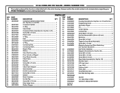
... 57 1 Nail Pusher Assembly 1 Magazine Assembly (Inc. Key No. 58 1 Screw (M4 x 6 mm 1 Screw (M4 x 12 mm 1 Screw (M2.6 x 6 mm 1 Edge Guide Assembly (Inc. Key No. 50 1 Airstrike Label 2 LED Light Label 1 Logo Label 1 Fastener Label 1 Data Label 1 Scale Marking Label 1 Nail Slide Warning Label 1 Seal Kit 1 in all correspondence regarding your RYOBI PIN NAILER or when ordering repair parts. KEY PART NO. 23 GA CORDLESS PIN NAILER - Nails (Pack of 500) Operator's Manual (961152787) MODEL NUMBER P318 The model number will be...
... 57 1 Nail Pusher Assembly 1 Magazine Assembly (Inc. Key No. 58 1 Screw (M4 x 6 mm 1 Screw (M4 x 12 mm 1 Screw (M2.6 x 6 mm 1 Edge Guide Assembly (Inc. Key No. 50 1 Airstrike Label 2 LED Light Label 1 Logo Label 1 Fastener Label 1 Data Label 1 Scale Marking Label 1 Nail Slide Warning Label 1 Seal Kit 1 in all correspondence regarding your RYOBI PIN NAILER or when ordering repair parts. KEY PART NO. 23 GA CORDLESS PIN NAILER - Nails (Pack of 500) Operator's Manual (961152787) MODEL NUMBER P318 The model number will be...


