English Manual
Page 1
PORTABLE PLANER AP1301 Your portable planer has been engineered and manufactured to our high standard for your purchase. WARNING: To reduce the risk of operation, and operator safety. OPERATOR'S MANUAL 13 in. Thank you years of rugged, trouble-free performance. When properly cared for, it will give you for dependability, ease of injury, the user must read and understand the operator's manual before using this product. SAVE THIS MANUAL FOR FUTURE REFERENCE
PORTABLE PLANER AP1301 Your portable planer has been engineered and manufactured to our high standard for your purchase. WARNING: To reduce the risk of operation, and operator safety. OPERATOR'S MANUAL 13 in. Thank you years of rugged, trouble-free performance. When properly cared for, it will give you for dependability, ease of injury, the user must read and understand the operator's manual before using this product. SAVE THIS MANUAL FOR FUTURE REFERENCE
English Manual
Page 13
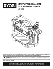
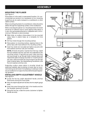
...long enough to go through holes in planer base, the material being mounted to , and the lock washers and hex nuts. MOUNTING BOARD WORKBENCH Fig. 4 DEPTH ADJUSTMENT HANDLE WITH SCREW Fig. 5 13 ASSEMBLY MOUNTING THE PLANER See Figure 4. If the planer is to be easily clamped to ...avoid tipping while planer is in a permanent location, it to a workbench or to be drilled through the mounting surface....
...long enough to go through holes in planer base, the material being mounted to , and the lock washers and hex nuts. MOUNTING BOARD WORKBENCH Fig. 4 DEPTH ADJUSTMENT HANDLE WITH SCREW Fig. 5 13 ASSEMBLY MOUNTING THE PLANER See Figure 4. If the planer is to be easily clamped to ...avoid tipping while planer is in a permanent location, it to a workbench or to be drilled through the mounting surface....
English Manual
Page 14
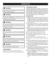
...with dull or nicked cutter blades may produce ridges or rough workpiece surfaces. Gum and pitch on materials not recommended may damage the planer and may use of solid wood and wood products THICKNESS PLANING Thickness planing sizes the workpiece to a desired thickness while creating a smooth, level... Do not lower the cutter head assembly lower than 3/4 in possible serious injury. Do not plane workpieces that a careless fraction of cut (13 in ., make you careless. Whenever working with a new type of wood, make thin test cuts on how to remove and replace or turn the...
...with dull or nicked cutter blades may produce ridges or rough workpiece surfaces. Gum and pitch on materials not recommended may damage the planer and may use of solid wood and wood products THICKNESS PLANING Thickness planing sizes the workpiece to a desired thickness while creating a smooth, level... Do not lower the cutter head assembly lower than 3/4 in possible serious injury. Do not plane workpieces that a careless fraction of cut (13 in ., make you careless. Whenever working with a new type of wood, make thin test cuts on how to remove and replace or turn the...
English Manual
Page 16
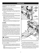
...adjustment handle counterclockwise to lower the cutter head to the current depth of the planer. for material between 6 in . and 13 in this direction. Use scrap wood for accuracy. Before each use the planer at the maximum depth of the planer infeed area. Turn switch ON ( l ). Lift ...retightening any portion of the board which has not gone past the outfeed area of the handle will damage the motor. If the planer sounds excessively loud or has excessive vibration, turn off the machine immediately and check again for material up to function properly. Each full...
...adjustment handle counterclockwise to lower the cutter head to the current depth of the planer. for material between 6 in . and 13 in this direction. Use scrap wood for accuracy. Before each use the planer at the maximum depth of the planer infeed area. Turn switch ON ( l ). Lift ...retightening any portion of the board which has not gone past the outfeed area of the handle will damage the motor. If the planer sounds excessively loud or has excessive vibration, turn off the machine immediately and check again for material up to function properly. Each full...
English Manual
Page 19
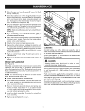
... will be effective. Never replace one side without replacing the other debris can cause the tool to secure. BRUSH BRUSH CAP Fig. 13 CLEANING Sawdust buildup and other . Install new brush assembly, if required, or reinstall old brush assembly. Replace cap... feed rollers after each blade before installing. Place blade into the wood and interfere with a light coating of carbon remains on the planer. Replace both brush assemblies. The brush assembly is parallel to the cutter head slot. Retighten the blade locking screws securely. ...
... will be effective. Never replace one side without replacing the other debris can cause the tool to secure. BRUSH BRUSH CAP Fig. 13 CLEANING Sawdust buildup and other . Install new brush assembly, if required, or reinstall old brush assembly. Replace cap... feed rollers after each blade before installing. Place blade into the wood and interfere with a light coating of carbon remains on the planer. Replace both brush assemblies. The brush assembly is parallel to the cutter head slot. Retighten the blade locking screws securely. ...
English Manual
Page 22
PORTABLE PLANER AP1301 • SERVICE Now that you call 1-800-525-2579 for a complete list of Authorized Service Centers. • MODEL NO. AND SERIAL NO. Please record the ... service, simply contact your nearest Authorized Service Center. OPERATOR'S MANUAL 13 in the space provided below. • HOW TO ORDER REPAIR PARTS When ordering repair parts, always give the following information: • MODEL NUMBER AP1301 • SERIAL NUMBER Ryobi® is a registered trademark of Ryobi® Limited used under license. 983000-828 9-10-07...
PORTABLE PLANER AP1301 • SERVICE Now that you call 1-800-525-2579 for a complete list of Authorized Service Centers. • MODEL NO. AND SERIAL NO. Please record the ... service, simply contact your nearest Authorized Service Center. OPERATOR'S MANUAL 13 in the space provided below. • HOW TO ORDER REPAIR PARTS When ordering repair parts, always give the following information: • MODEL NUMBER AP1301 • SERIAL NUMBER Ryobi® is a registered trademark of Ryobi® Limited used under license. 983000-828 9-10-07...
Repair Sheet
Page 3
RYOBI 13 in all correspondence regarding your PLANER or when ordering repair parts. Always mention the model number in . KEY NOS. 2-6 AND 91 1 HANDLE KNOB ASSEMBLY 1 HANDLE ARM ASSEMBLY 1 * SCREW (M5 X P0.8 X 20 ...-1 1 WARNING LABEL (DUST CHUTE-2 1 WARNING LABEL (DUST CHUTE-3 1 CHUTE DUST (INC. LONG (OD.20 X 1.0t X 485 mm 2 * SCREW (M6 X P1 X 60 mm SOC. MODEL NUMBER AP1301 The model number will be found on a plate attached to the motor housing. KEY NOS. 26-28 1 HOOD DOOR 1 HURRICANE KNOB 2 * SCREW (M5 X P0.8 X 10...
RYOBI 13 in all correspondence regarding your PLANER or when ordering repair parts. Always mention the model number in . KEY NOS. 2-6 AND 91 1 HANDLE KNOB ASSEMBLY 1 HANDLE ARM ASSEMBLY 1 * SCREW (M5 X P0.8 X 20 ...-1 1 WARNING LABEL (DUST CHUTE-2 1 WARNING LABEL (DUST CHUTE-3 1 CHUTE DUST (INC. LONG (OD.20 X 1.0t X 485 mm 2 * SCREW (M6 X P1 X 60 mm SOC. MODEL NUMBER AP1301 The model number will be found on a plate attached to the motor housing. KEY NOS. 26-28 1 HOOD DOOR 1 HURRICANE KNOB 2 * SCREW (M5 X P0.8 X 10...
Repair Sheet
Page 4
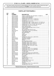
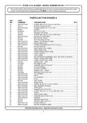
RYOBI 13 in all correspondence regarding your PLANER or when ordering repair parts. PLANER - KEY NOS. 66 AND 95) ......... 1 SMALL COVER (LEFT SIDE 1 LARGE COVER ... 827757 089170101103 089170101906 PARTS LIST FOR FIGURE A DESCRIPTION QTY. * SCREW (M8 X P1.25 X 20 mm HEX HD 1 BLADE LOCKING PLATE 2 PLANER BLADE (19 X 1.8 X 344 2 SCREW 14 KEY (5 X 12 mm 1 BEARING RETAINER 1 * SCREW (M5 X P0.8 X 12 mm...2 SPROCKET 2 * WASHER (Ø4 X Ø15 X 2t 2 * SCREW (M4 X P0.7 X 12 mm HEX SOC. MODEL NUMBER AP1301 The model number will be found on a plate attached to the motor housing.
RYOBI 13 in all correspondence regarding your PLANER or when ordering repair parts. PLANER - KEY NOS. 66 AND 95) ......... 1 SMALL COVER (LEFT SIDE 1 LARGE COVER ... 827757 089170101103 089170101906 PARTS LIST FOR FIGURE A DESCRIPTION QTY. * SCREW (M8 X P1.25 X 20 mm HEX HD 1 BLADE LOCKING PLATE 2 PLANER BLADE (19 X 1.8 X 344 2 SCREW 14 KEY (5 X 12 mm 1 BEARING RETAINER 1 * SCREW (M5 X P0.8 X 12 mm...2 SPROCKET 2 * WASHER (Ø4 X Ø15 X 2t 2 * SCREW (M4 X P0.7 X 12 mm HEX SOC. MODEL NUMBER AP1301 The model number will be found on a plate attached to the motor housing.
Repair Sheet
Page 6
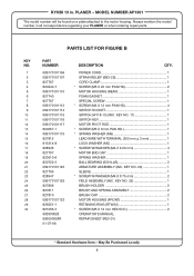
...-6 820722-3 089170101126 827706 828947 089170101129 827809 827811 827810 089170101133 826551-1 821065-3 983000828 983000828R 01-27-06 DESCRIPTION QTY. RYOBI 13 in all correspondence regarding your PLANER or when ordering repair parts. POWER CORD 1 STRAIN RELIEF (6B3-2S 1 CORD CLAMP 1 * SCREW (M5 ...X 20 mm PAN HD 2 MOTOR HOUSING (REAR 1 FOAM GASKET 1 SPECIAL SCREW 1 * SCREW (M4 X 12 mm PAN HD 4 SWITCH SOCKET 1 SWITCH (HY18-13) (INC. May Be Purchased Locally 6 MODEL NUMBER AP1301...
...-6 820722-3 089170101126 827706 828947 089170101129 827809 827811 827810 089170101133 826551-1 821065-3 983000828 983000828R 01-27-06 DESCRIPTION QTY. RYOBI 13 in all correspondence regarding your PLANER or when ordering repair parts. POWER CORD 1 STRAIN RELIEF (6B3-2S 1 CORD CLAMP 1 * SCREW (M5 ...X 20 mm PAN HD 2 MOTOR HOUSING (REAR 1 FOAM GASKET 1 SPECIAL SCREW 1 * SCREW (M4 X 12 mm PAN HD 4 SWITCH SOCKET 1 SWITCH (HY18-13) (INC. May Be Purchased Locally 6 MODEL NUMBER AP1301...
Repair Sheet
Page 7
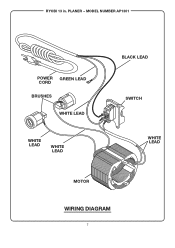
MODEL NUMBER AP1301 POWER GREEN LEAD CORD BRUSHES WHITE LEAD WHITE LEAD WHITE LEAD BLACK LEAD SWITCH WHITE LEAD MOTOR WIRING DIAGRAM 7 RYOBI 13 in. PLANER -
MODEL NUMBER AP1301 POWER GREEN LEAD CORD BRUSHES WHITE LEAD WHITE LEAD WHITE LEAD BLACK LEAD SWITCH WHITE LEAD MOTOR WIRING DIAGRAM 7 RYOBI 13 in. PLANER -


