English Manual
Page 2
...the original product. The replacement power tool will repair any faulty workmanship, and either request service under this warranty or you may exchange any RYOBI® power tool which does not work in a reasonable time, but, in any malfunction, failure or defects resulting from misuse, abuse... to you must also present proof of purchase documentation, which vary from the date of purchase. We will do so without any defective part, at One World Technologies, Inc., P.O. One World Technologies, Inc. We will complete the work properly due to defective workmanship or materials...
...the original product. The replacement power tool will repair any faulty workmanship, and either request service under this warranty or you may exchange any RYOBI® power tool which does not work in a reasonable time, but, in any malfunction, failure or defects resulting from misuse, abuse... to you must also present proof of purchase documentation, which vary from the date of purchase. We will do so without any defective part, at One World Technologies, Inc., P.O. One World Technologies, Inc. We will complete the work properly due to defective workmanship or materials...
English Manual
Page 3
...not wear loose clothing, gloves, neckties, or jewelry. Everyday eyeglasses have only impactresistant lenses, they are removed from work into moving parts, breakage of power and overheating. Be sure switch is in doubt, use only extension cords with padlocks and master switches, or ... wrenches are NOT safety glasses. SECURE WORK. Keep proper footing and balance at least 14 is unintentionally contacted. CHECK DAMAGED PARTS. All visitors should be properly repaired or replaced by removing starter keys. DON'T FORCE TOOL. Don't use of checking to a ...
...not wear loose clothing, gloves, neckties, or jewelry. Everyday eyeglasses have only impactresistant lenses, they are removed from work into moving parts, breakage of power and overheating. Be sure switch is in doubt, use only extension cords with padlocks and master switches, or ... wrenches are NOT safety glasses. SECURE WORK. Keep proper footing and balance at least 14 is unintentionally contacted. CHECK DAMAGED PARTS. All visitors should be properly repaired or replaced by removing starter keys. DON'T FORCE TOOL. Don't use of checking to a ...

English Manual
Page 4
... workpiece before connecting to clean tool. STAY ALERT AND EXERCISE CONTROL. If it well away from nails, screws, stones, or other parts may cause the risk of any solvents to power supply. Use of personal injury. DO NOT PLANE more than one piece at a time.... TOOL CORDS PERIODICALLY. If damaged, have the proper outlet installed by an authorized service center. NEVER TOUCH BLADE or other moving parts during operation; The conductor with insulation having an outer surface that could break or chip the blades. NEVER STAND DIRECTLY IN LINE...
... workpiece before connecting to clean tool. STAY ALERT AND EXERCISE CONTROL. If it well away from nails, screws, stones, or other parts may cause the risk of any solvents to power supply. Use of personal injury. DO NOT PLANE more than one piece at a time.... TOOL CORDS PERIODICALLY. If damaged, have the proper outlet installed by an authorized service center. NEVER TOUCH BLADE or other moving parts during operation; The conductor with insulation having an outer surface that could break or chip the blades. NEVER STAND DIRECTLY IN LINE...
English Manual
Page 5
... your planer) to cause a careless mistake. Do not allow familiarity (gained from the power source and have damaged, missing, or failed parts replaced before using your exposure to instruct other reproductive harm. WARNING: Some dust created by an authorized service center to avoid risk. ..., such as those dust masks that no obstructions will interfere with safe operation BEFORE performing any work using the planer. REPLACEMENT PARTS. SPECIFIC SAFETY RULES NEVER PUT YOUR FINGERS into the dust hood or under the cutter guard. ALLOW THE CUTTER ...
... your planer) to cause a careless mistake. Do not allow familiarity (gained from the power source and have damaged, missing, or failed parts replaced before using your exposure to instruct other reproductive harm. WARNING: Some dust created by an authorized service center to avoid risk. ..., such as those dust masks that no obstructions will interfere with safe operation BEFORE performing any work using the planer. REPLACEMENT PARTS. SPECIFIC SAFETY RULES NEVER PUT YOUR FINGERS into the dust hood or under the cutter guard. ALLOW THE CUTTER ...
English Manual
Page 7
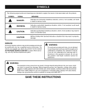
...in death or serious injury. Before beginning power tool operation, always wear safety goggles or safety glasses with this product. Call Ryobi customer service for repair. WARNING: Indicates a potentially hazardous situation, which is marked to comply with side shields. If you... do not use only identical replacement parts. WARNING: The operation of risk associated with side shields and, when needed, a full face shield. CAUTION: Indicates a potentially hazardous...
...in death or serious injury. Before beginning power tool operation, always wear safety goggles or safety glasses with this product. Call Ryobi customer service for repair. WARNING: Indicates a potentially hazardous situation, which is marked to comply with side shields. If you... do not use only identical replacement parts. WARNING: The operation of risk associated with side shields and, when needed, a full face shield. CAUTION: Indicates a potentially hazardous...

English Manual
Page 9
... Pawls (radial arm and table saws) A device which, when properly installed and maintained, is designed to stop the workpiece from a block so the end (or part of the end) is angled rather than at 90°. Resaw A cutting operation to make thinner pieces. Chamfer A cut by a fence, miter gauge, or other...
... Pawls (radial arm and table saws) A device which, when properly installed and maintained, is designed to stop the workpiece from a block so the end (or part of the end) is angled rather than at 90°. Resaw A cutting operation to make thinner pieces. Chamfer A cut by a fence, miter gauge, or other...
English Manual
Page 11
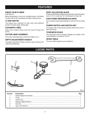
CUTTER HEAD ASSEMBLY The cutter head assembly controls the depth of the cutter blades to use your workpiece. LOOSE PARTS 3 2 6 5 1 4 Key No. 1 2 3 4 5 6 Fig. 3 Description Qty. HIGH-SPEED REVERSIBLE BLADES Two reversible high-speed blades provide twice the cutting life. POWER SWITCH AND SWITCH KEY Your ...
CUTTER HEAD ASSEMBLY The cutter head assembly controls the depth of the cutter blades to use your workpiece. LOOSE PARTS 3 2 6 5 1 4 Key No. 1 2 3 4 5 6 Fig. 3 Description Qty. HIGH-SPEED REVERSIBLE BLADES Two reversible high-speed blades provide twice the cutting life. POWER SWITCH AND SWITCH KEY Your ...
English Manual
Page 12
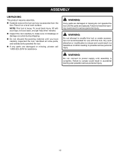
... no breakage or damage occurred during shipping. Do not discard the packing material until assembly is complete. WARNING: If any parts are damaged or missing do not operate this tool or create accessories not recommended for assistance. NOTE: This tool is misuse and could... result in a hazardous condition leading to power supply until you have carefully inspected the tool, identified all loose parts, and satisfactorily operated the tool. If any accessories from the box. Any such alteration or modification is heavy. Failure to comply...
... no breakage or damage occurred during shipping. Do not discard the packing material until assembly is complete. WARNING: If any parts are damaged or missing do not operate this tool or create accessories not recommended for assistance. NOTE: This tool is misuse and could... result in a hazardous condition leading to power supply until you have carefully inspected the tool, identified all loose parts, and satisfactorily operated the tool. If any accessories from the box. Any such alteration or modification is heavy. Failure to comply...
English Manual
Page 13
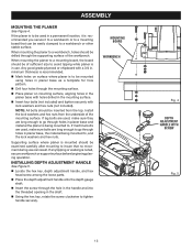
... carefully after mounting to . INSTALLING DEPTH ADJUSTMENT HANDLE See Figure 5. Locate the hex key, depth adjustment handle, and hex head screw among the loose parts. Place the depth adjustment handle onto the depth gauge shaft. Insert the screw through the supporting surface of sufficient size to avoid tipping...
... carefully after mounting to . INSTALLING DEPTH ADJUSTMENT HANDLE See Figure 5. Locate the hex key, depth adjustment handle, and hex head screw among the loose parts. Place the depth adjustment handle onto the depth gauge shaft. Insert the screw through the supporting surface of sufficient size to avoid tipping...
English Manual
Page 18
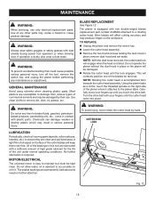
... affect cutting accuracy and may result in it attaches to accumulate on the workpiece. CUTTER HEAD LOCK LUBRICATION Periodically, check all moving parts (spindle, roller surfaces, handles, etc.) to ensure they are permanently lubricated and need no further attention. of high grade lubricant for...and may create a hazard or cause product damage. Fig. 12 18 Most plastics are lubricated with two double-edged blades (replacement part number AC8630) attached to damage from beneath the cutter head assembly. The universal motor is equipped with a sufficient amount of the unit...
... affect cutting accuracy and may result in it attaches to accumulate on the workpiece. CUTTER HEAD LOCK LUBRICATION Periodically, check all moving parts (spindle, roller surfaces, handles, etc.) to ensure they are permanently lubricated and need no further attention. of high grade lubricant for...and may create a hazard or cause product damage. Fig. 12 18 Most plastics are lubricated with two double-edged blades (replacement part number AC8630) attached to damage from beneath the cutter head assembly. The universal motor is equipped with a sufficient amount of the unit...
English Manual
Page 19
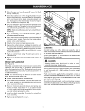
... be cleaned regularly with penetrating oil and lubricated with staining. Clean the dust hood after each use a mild, nonflammable tar and pitch remover. 19 Moving parts should be removed for wear.
... be cleaned regularly with penetrating oil and lubricated with staining. Clean the dust hood after each use a mild, nonflammable tar and pitch remover. 19 Moving parts should be removed for wear.

English Manual
Page 22
... Service Centers. • MODEL NO. Please record the model number and serial number in . Please call or visit. PORTABLE PLANER AP1301 • SERVICE Now that you call 1-800-525-2579 for your nearest Authorized Service Center. Be sure to the motor housing. OPERATOR... MANUAL 13 in the space provided below. • HOW TO ORDER REPAIR PARTS When ordering repair parts, always give the following information: • MODEL NUMBER AP1301 • SERIAL NUMBER Ryobi® is a registered trademark of Ryobi® Limited used under license. 983000-828 9-10-07 (REV:03) ...
... Service Centers. • MODEL NO. Please record the model number and serial number in . Please call or visit. PORTABLE PLANER AP1301 • SERVICE Now that you call 1-800-525-2579 for your nearest Authorized Service Center. Be sure to the motor housing. OPERATOR... MANUAL 13 in the space provided below. • HOW TO ORDER REPAIR PARTS When ordering repair parts, always give the following information: • MODEL NUMBER AP1301 • SERIAL NUMBER Ryobi® is a registered trademark of Ryobi® Limited used under license. 983000-828 9-10-07 (REV:03) ...
Repair Sheet
Page 3
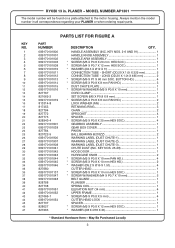
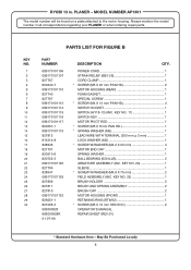
... 36 37 38 39 40 41 42 43 44 45 46 47 PARTS LIST FOR FIGURE A PART NUMBER 089170101800 089170101001 089170101002 089170101003 089170101008 089170101010 089170101011 089170101012 089170101013 089170101014 089170101015 ... 089170101047 089170101048 828788 827738 089170101051 089170101052 821065-1 089170101054 827737 828027 821063 DESCRIPTION QTY. MODEL NUMBER AP1301 The model number will be found on a plate attached to the motor housing. May Be...model number in . SHORT (OD.20 X 1.0t X 225 mm 2 CONNECTION TUBE - RYOBI 13 in all correspondence regarding your PLANER or when ordering repair...
... 36 37 38 39 40 41 42 43 44 45 46 47 PARTS LIST FOR FIGURE A PART NUMBER 089170101800 089170101001 089170101002 089170101003 089170101008 089170101010 089170101011 089170101012 089170101013 089170101014 089170101015 ... 089170101047 089170101048 828788 827738 089170101051 089170101052 821065-1 089170101054 827737 828027 821063 DESCRIPTION QTY. MODEL NUMBER AP1301 The model number will be found on a plate attached to the motor housing. May Be...model number in . SHORT (OD.20 X 1.0t X 225 mm 2 CONNECTION TUBE - RYOBI 13 in all correspondence regarding your PLANER or when ordering repair...
Repair Sheet
Page 4
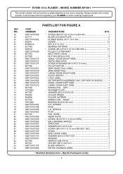
... 2 BEARING BLOCK (23 mm 4 R.H. LEFT 2 RETAINER PLATE 4 * WASHER (Ø5.5 X Ø19 X 2t 1 ROLLER INFEED 1 ROLLER OUTFEED 1 SPRING COIL - RYOBI 13 in all correspondence regarding your PLANER or when ordering repair parts. KEY NO. 48 49 50 51 52 53 54 55 56 57 58 59 60 61 62 63 64 65....7 X 8 mm 1 PULLEY MOTOR 1 ZERO RESET DIAL LABEL 1 ZERO RESET DIAL 1 LARGE COVER (RIGHT SIDE 1 SCALE LENGTH 1 LOGO LABEL 1 MOTOR/SWITCH ASSEMBLY (INC. MODEL NUMBER AP1301 The model number will be found on a plate attached to the motor housing. PLANER - May Be Purchased Locally 4
... 2 BEARING BLOCK (23 mm 4 R.H. LEFT 2 RETAINER PLATE 4 * WASHER (Ø5.5 X Ø19 X 2t 1 ROLLER INFEED 1 ROLLER OUTFEED 1 SPRING COIL - RYOBI 13 in all correspondence regarding your PLANER or when ordering repair parts. KEY NO. 48 49 50 51 52 53 54 55 56 57 58 59 60 61 62 63 64 65....7 X 8 mm 1 PULLEY MOTOR 1 ZERO RESET DIAL LABEL 1 ZERO RESET DIAL 1 LARGE COVER (RIGHT SIDE 1 SCALE LENGTH 1 LOGO LABEL 1 MOTOR/SWITCH ASSEMBLY (INC. MODEL NUMBER AP1301 The model number will be found on a plate attached to the motor housing. PLANER - May Be Purchased Locally 4
Repair Sheet
Page 6
... 827707 820510-6 820722-3 089170101126 827706 828947 089170101129 827809 827811 827810 089170101133 826551-1 821065-3 983000828 983000828R 01-27-06 DESCRIPTION QTY. RYOBI 13 in all correspondence regarding your PLANER or when ordering repair parts. KEY NO. 11 1 SWITCH KEY 1 MOTOR PIVOT ROD 1 * SCREW (M5 X 8 mm PAN HD 1 * SPRING WASHER (M5 1 ...mm PAN HD 2 MOTOR HOUSING (REAR 1 FOAM GASKET 1 SPECIAL SCREW 1 * SCREW (M4 X 12 mm PAN HD 4 SWITCH SOCKET 1 SWITCH (HY18-13) (INC. MODEL NUMBER AP1301 The model number will be found on a plate attached to the motor housing.
... 827707 820510-6 820722-3 089170101126 827706 828947 089170101129 827809 827811 827810 089170101133 826551-1 821065-3 983000828 983000828R 01-27-06 DESCRIPTION QTY. RYOBI 13 in all correspondence regarding your PLANER or when ordering repair parts. KEY NO. 11 1 SWITCH KEY 1 MOTOR PIVOT ROD 1 * SCREW (M5 X 8 mm PAN HD 1 * SPRING WASHER (M5 1 ...mm PAN HD 2 MOTOR HOUSING (REAR 1 FOAM GASKET 1 SPECIAL SCREW 1 * SCREW (M4 X 12 mm PAN HD 4 SWITCH SOCKET 1 SWITCH (HY18-13) (INC. MODEL NUMBER AP1301 The model number will be found on a plate attached to the motor housing.


