English Manual
Page 1
WARNING: To reduce the risk of operation, and operator safety. SAVE THIS MANUAL FOR FUTURE REFERENCE OPERATOR'S MANUAL MITER SAW STAND A18MS01 Your miter saw stand has been engineered and manufactured to Ryobi's high standard for buying a Ryobi product. Thank you years of rugged, trouble-free performance. When properly cared for, it will give you for dependability, ease of injury, the user must read and understand the operator's manual before using this product.
WARNING: To reduce the risk of operation, and operator safety. SAVE THIS MANUAL FOR FUTURE REFERENCE OPERATOR'S MANUAL MITER SAW STAND A18MS01 Your miter saw stand has been engineered and manufactured to Ryobi's high standard for buying a Ryobi product. Thank you years of rugged, trouble-free performance. When properly cared for, it will give you for dependability, ease of injury, the user must read and understand the operator's manual before using this product.
English Manual
Page 2
...workpiece together must not exceed 400 pounds. Do not apply an unbalanced load that no problems will accommodate many miter saws. WARNING: This stand is stable before plugging in . READ ALL INSTRUCTIONS Know your accessory. Cluttered work areas and work area clean. However, it is not... intended. This stand is designed to be used on the saw, perform a dry run of the cutting operation just to make sure that could cause the miter ...
...workpiece together must not exceed 400 pounds. Do not apply an unbalanced load that no problems will accommodate many miter saws. WARNING: This stand is stable before plugging in . READ ALL INSTRUCTIONS Know your accessory. Cluttered work areas and work area clean. However, it is not... intended. This stand is designed to be used on the saw, perform a dry run of the cutting operation just to make sure that could cause the miter ...
English Manual
Page 5
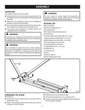
... n Push in .) (4) Flat Washers (4) Lock Washers (4) Nuts (4) Operator's Manual Warranty Registration Card LEG LOCKING PIN Fig. 2 preparing the stand n Repeat with the remaining three legs. n If any accessories from the box. WARNING: Do not attempt to modify this tool or create accessories... not recommended for use with the n Check to do not operate this tool. PACKING LIST Miter Saw Stand Saw Mounting Brackets (2) Work Supports (2) Work Support Mounting Brackets (2) Work Stops (2) Extension Adjustment Knobs (M8 x 25 mm) (2) Length Adjustment...
... n Push in .) (4) Flat Washers (4) Lock Washers (4) Nuts (4) Operator's Manual Warranty Registration Card LEG LOCKING PIN Fig. 2 preparing the stand n Repeat with the remaining three legs. n If any accessories from the box. WARNING: Do not attempt to modify this tool or create accessories... not recommended for use with the n Check to do not operate this tool. PACKING LIST Miter Saw Stand Saw Mounting Brackets (2) Work Supports (2) Work Support Mounting Brackets (2) Work Stops (2) Extension Adjustment Knobs (M8 x 25 mm) (2) Length Adjustment...
English Manual
Page 8
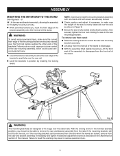
...front rail of this warning may result in the lowered (locked) position, you , lift the front part of the saw is evenly balanced over the stand rails. n With the assembly tilted slightly toward your body. With the locking levers in serious personal injury. 8 Failure to do so could... the other end of the bracket to fit snugly over the rails as described in position by lowering the locking levers. To remove saw from stand: n Raise the locking levers to unlock the saw and mounting bracket assembly. n Lift away from the saw and bracket assembly, allowing ...
...front rail of this warning may result in the lowered (locked) position, you , lift the front part of the saw is evenly balanced over the stand rails. n With the assembly tilted slightly toward your body. With the locking levers in serious personal injury. 8 Failure to do so could... the other end of the bracket to fit snugly over the rails as described in position by lowering the locking levers. To remove saw from stand: n Raise the locking levers to unlock the saw and mounting bracket assembly. n Lift away from the saw and bracket assembly, allowing ...
English Manual
Page 9
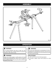
WARNING: Always wear safety goggles or safety glasses with tools to make you careless. ASSEMBLY lower locking levers to secure to stand Fig. 9 operation WARNING: Do not allow familiarity with side shields when operating tools. Remember that a careless fraction of this tool for the following purpose: ...
WARNING: Always wear safety goggles or safety glasses with tools to make you careless. ASSEMBLY lower locking levers to secure to stand Fig. 9 operation WARNING: Do not allow familiarity with side shields when operating tools. Remember that a careless fraction of this tool for the following purpose: ...
English Manual
Page 10
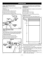
... extend the rails: n Loosen the extension adjustment knob. long. install screws. n Raise the work stop adjustment knob. n Pre-drill and countersink holes for the miter stand. away from the bottom corners of the strips as shown in each of the assembly. 10 Materials needed: n 9 x 20 in . n Align the two 3/4 x 6 in . plywood...
... extend the rails: n Loosen the extension adjustment knob. long. install screws. n Raise the work stop adjustment knob. n Pre-drill and countersink holes for the miter stand. away from the bottom corners of the strips as shown in each of the assembly. 10 Materials needed: n 9 x 20 in . n Align the two 3/4 x 6 in . plywood...
English Manual
Page 11
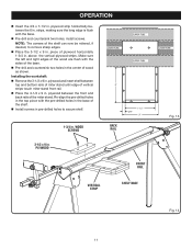
...-drilled holes in the top piece with the sides of wood as shown. plywood between the front and back rails of vertical 6" strips touch miter stand front rail. plywood 1-3/4 in . operation n Insert the 3/4 x 7-1/2 in . Re-align the pre-drilled holes in the base of the shelf. ...install screws. n Place the 3-1/2 x 9 in . plywood strip horizontally between top and bottom rails of miter stand until edge of the miter stand. n Place the 3-1/2 x 9 in . WOOD SCREWS back rail front rail vertical strip shelf base Fig. 13 Fig. 14 11 ...
...-drilled holes in the top piece with the sides of wood as shown. plywood between the front and back rails of vertical 6" strips touch miter stand front rail. plywood 1-3/4 in . operation n Insert the 3/4 x 7-1/2 in . Re-align the pre-drilled holes in the base of the shelf. ...install screws. n Place the 3-1/2 x 9 in . plywood strip horizontally between top and bottom rails of miter stand until edge of the miter stand. n Place the 3-1/2 x 9 in . WOOD SCREWS back rail front rail vertical strip shelf base Fig. 13 Fig. 14 11 ...
English Manual
Page 12
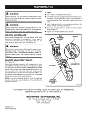
...SCREW screwdriver Fig. 15 To purchase additional saw should not be tightened or counterclockwise if the assembly needs to secure. A000220601), call Ryobi customer service at any other parts may result in the lowered (locked) position, you should be loosened. If the saw and ...bracket assembly will not fit over the stand rails. maintenance WARNING: When servicing, use . GENERAL MAINTENANCE Avoid using solvents when cleaning plastic parts. Most plastics are susceptible to ...
...SCREW screwdriver Fig. 15 To purchase additional saw should not be tightened or counterclockwise if the assembly needs to secure. A000220601), call Ryobi customer service at any other parts may result in the lowered (locked) position, you should be loosened. If the saw and ...bracket assembly will not fit over the stand rails. maintenance WARNING: When servicing, use . GENERAL MAINTENANCE Avoid using solvents when cleaning plastic parts. Most plastics are susceptible to ...
Repair Sheet
Page 3
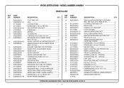
SPECIAL 2 SCREW B (PAN HD. - MODEL NUMBER A18MS01 PARTS LIST KEY NO. 1 2 3 4 5 6 7 8 9 10 11 12 13 14 15 16 17 18 19 20 21 22 23 24 25 26 27...M4 X 10 mm PAN HD 4 EXTENSION RAIL END CAP (INSIDE 2 * SCREW (M5 X 12 mm FLAT HD 4 EXTENSION RAIL LOCATOR BRACKET ...........2 MITER SAW STAND UPPER HANDLE 1 MITER SAW STAND LOWER HANDLE 1 * SCREW (M4 X 16 mm TRUSS HD 2 WORK FRAME ASSEMBLY 1 KEY NO. 29 30 31 32 33 34 35 36 37 38...REAR CLAMING JAW 1 FRONT CLAMPING JAW 1 SCREW A (PAN HD. - KEY NOS. 30-34 AND 36-47 2 LOCKING LEVER END CAP 1 RIGHT CAM 1 HANDLE, M.S. RYOBI MITER STAND -
SPECIAL 2 SCREW B (PAN HD. - MODEL NUMBER A18MS01 PARTS LIST KEY NO. 1 2 3 4 5 6 7 8 9 10 11 12 13 14 15 16 17 18 19 20 21 22 23 24 25 26 27...M4 X 10 mm PAN HD 4 EXTENSION RAIL END CAP (INSIDE 2 * SCREW (M5 X 12 mm FLAT HD 4 EXTENSION RAIL LOCATOR BRACKET ...........2 MITER SAW STAND UPPER HANDLE 1 MITER SAW STAND LOWER HANDLE 1 * SCREW (M4 X 16 mm TRUSS HD 2 WORK FRAME ASSEMBLY 1 KEY NO. 29 30 31 32 33 34 35 36 37 38...REAR CLAMING JAW 1 FRONT CLAMPING JAW 1 SCREW A (PAN HD. - KEY NOS. 30-34 AND 36-47 2 LOCKING LEVER END CAP 1 RIGHT CAM 1 HANDLE, M.S. RYOBI MITER STAND -