English Manual
Page 1
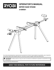
SAVE THIS MANUAL FOR FUTURE REFERENCE WARNING: To reduce the risk of operation, and operator safety. Thank you years of rugged, trouble-free performance. OPERATOR'S MANUAL MITER SAW STAND A18MS01 Your miter saw stand has been engineered and manufactured to Ryobi's high standard for buying a Ryobi product. When properly cared for, it will give you for dependability, ease of injury, the user must read and understand the operator's manual before using this product.
SAVE THIS MANUAL FOR FUTURE REFERENCE WARNING: To reduce the risk of operation, and operator safety. Thank you years of rugged, trouble-free performance. OPERATOR'S MANUAL MITER SAW STAND A18MS01 Your miter saw stand has been engineered and manufactured to Ryobi's high standard for buying a Ryobi product. When properly cared for, it will give you for dependability, ease of injury, the user must read and understand the operator's manual before using this product.
English Manual
Page 2
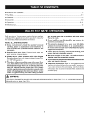
...cut is made. Do not modify or use this stand for which it should never be used is mounted securely and is designed for use with miter saws with a blade diameter not larger than 10 in ., or a slide miter saw stand to tip over. Save these instructions also to ...them frequently and use this operator's manual, the operator's manual for the table saw with a blade diameter larger than 10 in...
...cut is made. Do not modify or use this stand for which it should never be used is mounted securely and is designed for use with miter saws with a blade diameter not larger than 10 in ., or a slide miter saw stand to tip over. Save these instructions also to ...them frequently and use this operator's manual, the operator's manual for the table saw with a blade diameter larger than 10 in...
English Manual
Page 5
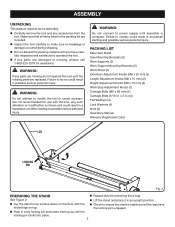
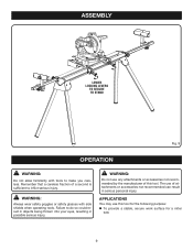
... 2 in.) (4) Flat Washers (4) Lock Washers (4) Nuts (4) Operator's Manual Warranty Registration Card LEG LOCKING PIN Fig. 2 preparing the stand n Repeat with the n Check to comply could result in the packing list are damaged or missing, please call 1-800-525-2579 for ...Failure to possible serious personal injury. WARNING: Do not attempt to make sure no breakage or damage occurred during shipping. PACKING LIST Miter Saw Stand Saw Mounting Brackets (2) Work Supports (2) Work Support Mounting Brackets (2) Work Stops (2) Extension Adjustment Knobs (M8 x 25 mm) (2) Length ...
... 2 in.) (4) Flat Washers (4) Lock Washers (4) Nuts (4) Operator's Manual Warranty Registration Card LEG LOCKING PIN Fig. 2 preparing the stand n Repeat with the n Check to comply could result in the packing list are damaged or missing, please call 1-800-525-2579 for ...Failure to possible serious personal injury. WARNING: Do not attempt to make sure no breakage or damage occurred during shipping. PACKING LIST Miter Saw Stand Saw Mounting Brackets (2) Work Supports (2) Work Support Mounting Brackets (2) Work Stops (2) Extension Adjustment Knobs (M8 x 25 mm) (2) Length ...
English Manual
Page 8
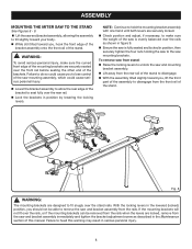
... in the lowered (locked) position, you to lose control of the stand to heed this manual. To remove saw from stand: n Raise the locking levers to remove the saw and bracket assembly from the rear rail of the saw and mounting bracket assembly. n Lift away from the rails. With...With the assembly tilted slightly toward you , lift the front part of the assembly to disengage from the front rail of the stand. ASSEMBLY MOUNTING THE MITER SAW TO THE STAND See Figures 8 - 9. n While still tilted toward you , hook the front edge of the bracket assembly onto the front rail ...
... in the lowered (locked) position, you to lose control of the stand to heed this manual. To remove saw from stand: n Raise the locking levers to remove the saw and bracket assembly from the rear rail of the saw and mounting bracket assembly. n Lift away from the rails. With...With the assembly tilted slightly toward you , lift the front part of the assembly to disengage from the front rail of the stand. ASSEMBLY MOUNTING THE MITER SAW TO THE STAND See Figures 8 - 9. n While still tilted toward you , hook the front edge of the bracket assembly onto the front rail ...
English Manual
Page 9
... attachments or accessories not recommended by the manufacturer of this tool for the following purpose: To provide a stable, secure work surface for a miter saw 9 Remember that a careless fraction of attachments or accessories not recommended can result in possible serious injury. WARNING: Do not use of a second is sufficient... do so could result in objects being thrown into your eyes, resulting in serious personal injury. ASSEMBLY lower locking levers to secure to stand Fig. 9 operation WARNING: Do not allow familiarity with side shields when operating tools.
... attachments or accessories not recommended by the manufacturer of this tool for the following purpose: To provide a stable, secure work surface for a miter saw 9 Remember that a careless fraction of attachments or accessories not recommended can result in possible serious injury. WARNING: Do not use of a second is sufficient... do so could result in objects being thrown into your eyes, resulting in serious personal injury. ASSEMBLY lower locking levers to secure to stand Fig. 9 operation WARNING: Do not allow familiarity with side shields when operating tools.
English Manual
Page 12
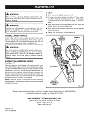
... bracket adjustment screws needs to be loosened. Mounting brackets are designed to slightly loosen the nut. If the saw and bracket assembly will not fit over the stand rails. Use of commercial solvents and may be removed from various types of any time let brake fluids, ...Avoid using solvents when cleaning plastic parts. Most plastics are locked, the bracket adjustment screws need to remove the saw mounting bracket assemblies (part no. A000220601), call Ryobi customer service at any other parts may result in contact with side shields during power tool operation or when ...
... bracket adjustment screws needs to be loosened. Mounting brackets are designed to slightly loosen the nut. If the saw and bracket assembly will not fit over the stand rails. Use of commercial solvents and may be removed from various types of any time let brake fluids, ...Avoid using solvents when cleaning plastic parts. Most plastics are locked, the bracket adjustment screws need to remove the saw mounting bracket assemblies (part no. A000220601), call Ryobi customer service at any other parts may result in contact with side shields during power tool operation or when ...
Repair Sheet
Page 3
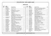
...4 * CARRIAGE BOLT (5/16-18 X 2 in 4 WARNING LABEL 2 OPERATOR'S MANUAL (9000225330501) REPAIR SHEET (REV:02) * STANDARD HARDWARE ITEM - MAY BE PURCHASED LOCALLY 3 RYOBI MITER STAND - MODEL NUMBER A18MS01 PARTS LIST KEY NO. 1 2 3 4 5 6 7 8 9 10 11 12 13 14 15 16 17 18 19 20 21 22 23 24 25 26 27 28 ...M4 X 10 mm PAN HD 4 EXTENSION RAIL END CAP (INSIDE 2 * SCREW (M5 X 12 mm FLAT HD 4 EXTENSION RAIL LOCATOR BRACKET ...........2 MITER SAW STAND UPPER HANDLE 1 MITER SAW STAND LOWER HANDLE 1 * SCREW (M4 X 16 mm TRUSS HD 2 WORK FRAME ASSEMBLY 1 KEY NO. 29 30 31 32 33 34 35 36 37 38 ...
...4 * CARRIAGE BOLT (5/16-18 X 2 in 4 WARNING LABEL 2 OPERATOR'S MANUAL (9000225330501) REPAIR SHEET (REV:02) * STANDARD HARDWARE ITEM - MAY BE PURCHASED LOCALLY 3 RYOBI MITER STAND - MODEL NUMBER A18MS01 PARTS LIST KEY NO. 1 2 3 4 5 6 7 8 9 10 11 12 13 14 15 16 17 18 19 20 21 22 23 24 25 26 27 28 ...M4 X 10 mm PAN HD 4 EXTENSION RAIL END CAP (INSIDE 2 * SCREW (M5 X 12 mm FLAT HD 4 EXTENSION RAIL LOCATOR BRACKET ...........2 MITER SAW STAND UPPER HANDLE 1 MITER SAW STAND LOWER HANDLE 1 * SCREW (M4 X 16 mm TRUSS HD 2 WORK FRAME ASSEMBLY 1 KEY NO. 29 30 31 32 33 34 35 36 37 38 ...


