English Manual
Page 4
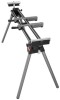
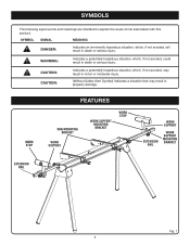
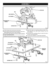
... hazardous situation, which , if not avoided, could result in death or serious injury. work stop FEATURES saw mounting bracket work support work support mounting bracket work stop work support extension rail work support mounting bracket extension rail Fig. 1 4 WARNING: Indicates a potentially hazardous situation, which , if not avoided, may result in minor or moderate...
... hazardous situation, which , if not avoided, could result in death or serious injury. work stop FEATURES saw mounting bracket work support work support mounting bracket work stop work support extension rail work support mounting bracket extension rail Fig. 1 4 WARNING: Indicates a potentially hazardous situation, which , if not avoided, may result in minor or moderate...
English Manual
Page 5
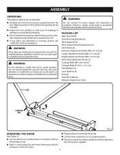
... list are replaced. n Do not discard the packing material until the locking pin clicks into place. 5 PACKING LIST Miter Saw Stand Saw Mounting Brackets (2) Work Supports (2) Work Support Mounting Brackets (2) Work Stops (2) Extension Adjustment Knobs (M8 x 25 mm) (2) Length Adjustment Knobs (M8 x 15 mm) (2) Height Adjustment Knobs (M8 x 15 mm) (2) Work Stop...
... list are replaced. n Do not discard the packing material until the locking pin clicks into place. 5 PACKING LIST Miter Saw Stand Saw Mounting Brackets (2) Work Supports (2) Work Support Mounting Brackets (2) Work Stops (2) Extension Adjustment Knobs (M8 x 25 mm) (2) Length Adjustment Knobs (M8 x 15 mm) (2) Height Adjustment Knobs (M8 x 15 mm) (2) Work Stop...
English Manual
Page 6
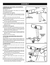
... to the saw . n Insert the height adjustment knob through the small hole on the side of the miter saw 's mounting feet. ATTACHING SAW mounting BRACKETS See Figures 6 - 7. Make sure bolts do not extend above the table of the work supports help balance the workpiece during cutting operations. n Feed ...through the opening in the down position. If the saw has holes that the extension rail extends through the other side of the same bracket. n Repeat with the opening in place using a flat washer, lock washer and nut. Always position the saw must be bolted to secure....
... to the saw . n Insert the height adjustment knob through the small hole on the side of the miter saw 's mounting feet. ATTACHING SAW mounting BRACKETS See Figures 6 - 7. Make sure bolts do not extend above the table of the work supports help balance the workpiece during cutting operations. n Feed ...through the opening in the down position. If the saw has holes that the extension rail extends through the other side of the same bracket. n Repeat with the opening in place using a flat washer, lock washer and nut. Always position the saw must be bolted to secure....
English Manual
Page 7
... parallel to each other, finger tighten all four nuts to a mounting surface at least 1/2 in the saw mounting brackets: n Unplug the saw and lock saw mounting brackets. n Drill holes in the mounting surface to match the slots in the saw arm in position. n Mount the saw to hold in the down ...p osition. NUT LOCK WASHER flat WASHER NUT LOCK WASHER flat WASHER SAW MOUNTING BRACKET MITER SAW SLOT MOUNTING SURFACE CARRIAGE BOLT 7 Fig. 7 n Proceed with the slots in . ASSEMBLY NUT LOCK WASHER flat WASHER MITER SAW SAW MOUNTing...
... parallel to each other, finger tighten all four nuts to a mounting surface at least 1/2 in the saw mounting brackets: n Unplug the saw and lock saw mounting brackets. n Drill holes in the mounting surface to match the slots in the saw arm in position. n Mount the saw to hold in the down ...p osition. NUT LOCK WASHER flat WASHER NUT LOCK WASHER flat WASHER SAW MOUNTING BRACKET MITER SAW SLOT MOUNTING SURFACE CARRIAGE BOLT 7 Fig. 7 n Proceed with the slots in . ASSEMBLY NUT LOCK WASHER flat WASHER MITER SAW SAW MOUNTing...
English Manual
Page 8
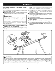
n While still tilted toward your body. WARNING: To avoid serious personal injury, make sure the weight of the brackets. NOTE: Continue to hold the mounting bracket assembly with one hand until both levers are designed to fit snugly over the front rail before seating the other end of the... stand to heed this manual. n Check position and adjust, if necessary, to do so could cause serious personal injury. n Ensure the saw and bracket assembly from the rear rail of this warning may result in position by lowering the locking levers. With the locking levers in figure 9. n Lock the...
n While still tilted toward your body. WARNING: To avoid serious personal injury, make sure the weight of the brackets. NOTE: Continue to hold the mounting bracket assembly with one hand until both levers are designed to fit snugly over the front rail before seating the other end of the... stand to heed this manual. n Check position and adjust, if necessary, to do so could cause serious personal injury. n Ensure the saw and bracket assembly from the rear rail of this warning may result in position by lowering the locking levers. With the locking levers in figure 9. n Lock the...
English Manual
Page 12
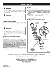
..., Anderson, SC 29625 Phone 1-800-525-2579 www.ryobitools.com Mounting brackets are susceptible to tighten or loosen the bracket adjustment screws. If the saw should not be removed from the mounting brackets before attempting to damage from the rails. A000220601), call Ryobi customer service at any other parts may be tightened. With the...
..., Anderson, SC 29625 Phone 1-800-525-2579 www.ryobitools.com Mounting brackets are susceptible to tighten or loosen the bracket adjustment screws. If the saw should not be removed from the mounting brackets before attempting to damage from the rails. A000220601), call Ryobi customer service at any other parts may be tightened. With the...
Repair Sheet
Page 3
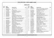
MODEL NUMBER A18MS01 PARTS LIST KEY NO. 1 2 3 4 5 6 7 8 9...10 mm PAN HD 4 EXTENSION RAIL END CAP (INSIDE 2 * SCREW (M5 X 12 mm FLAT HD 4 EXTENSION RAIL LOCATOR BRACKET ...........2 MITER SAW STAND UPPER HANDLE 1 MITER SAW STAND LOWER HANDLE 1 * SCREW (M4 X 16 mm TRUSS HD 2 WORK FRAME...411012706 412022706 412012704 410032716 9000225330201 983000710 983000710R 4-10-06 DESCRIPTION QTY SAW MOUNTING BRACKET ASSEMBLY (INC. SPECIAL 2 SCREW B (PAN HD. - RYOBI MITER STAND - MAY BE PURCHASED LOCALLY 3 SPECIAL 1 LEFT CAM 1 MOUNTING BRACKET SCREW SET 1 * HEX NUT (5/16 in 4 * WASHER (5/16...
MODEL NUMBER A18MS01 PARTS LIST KEY NO. 1 2 3 4 5 6 7 8 9...10 mm PAN HD 4 EXTENSION RAIL END CAP (INSIDE 2 * SCREW (M5 X 12 mm FLAT HD 4 EXTENSION RAIL LOCATOR BRACKET ...........2 MITER SAW STAND UPPER HANDLE 1 MITER SAW STAND LOWER HANDLE 1 * SCREW (M4 X 16 mm TRUSS HD 2 WORK FRAME...411012706 412022706 412012704 410032716 9000225330201 983000710 983000710R 4-10-06 DESCRIPTION QTY SAW MOUNTING BRACKET ASSEMBLY (INC. SPECIAL 2 SCREW B (PAN HD. - RYOBI MITER STAND - MAY BE PURCHASED LOCALLY 3 SPECIAL 1 LEFT CAM 1 MOUNTING BRACKET SCREW SET 1 * HEX NUT (5/16 in 4 * WASHER (5/16...
