English Manual
Page 4
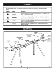
... meanings are intended to explain the levels of risk associated with this product. work stop FEATURES saw mounting bracket work support work support mounting bracket work stop work support extension rail work support mounting bracket extension rail Fig. 1 4 CAUTION: CAUTION: Indicates a potentially hazardous situation, which, if not avoided, may result in minor or...
... meanings are intended to explain the levels of risk associated with this product. work stop FEATURES saw mounting bracket work support work support mounting bracket work stop work support extension rail work support mounting bracket extension rail Fig. 1 4 CAUTION: CAUTION: Indicates a potentially hazardous situation, which, if not avoided, may result in minor or...
English Manual
Page 5
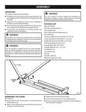
... sure no breakage or damage occurred during shipping. n Lay the stand's top surface down on top. PACKING LIST Miter Saw Stand Saw Mounting Brackets (2) Work Supports (2) Work Support Mounting Brackets (2) Work Stops (2) Extension Adjustment Knobs (M8 x 25 mm) (2) Length Adjustment Knobs (M8 x 15 mm) (2) Height Adjustment Knobs (M8 x 15 mm) (2) Work Stop...
... sure no breakage or damage occurred during shipping. n Lay the stand's top surface down on top. PACKING LIST Miter Saw Stand Saw Mounting Brackets (2) Work Supports (2) Work Support Mounting Brackets (2) Work Stops (2) Extension Adjustment Knobs (M8 x 25 mm) (2) Length Adjustment Knobs (M8 x 15 mm) (2) Height Adjustment Knobs (M8 x 15 mm) (2) Work Stop...
English Manual
Page 6
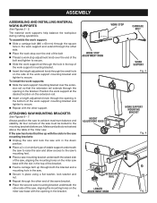
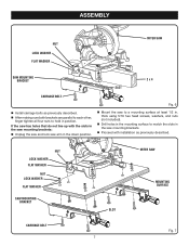
... hole in the bottom of the miter saw to secure. Always position the saw . n Feed a carriage bolt up with the other side. ATTACHING SAW mounting BRACKETS See Figures 6 - 7. n Place a 2 x 4 or similar type of the saw 's mounting feet. All four corners of stable support underneath the saw to ... knob over the extension rail so that line up through the small hole on the miter saw . n Insert the height adjustment knob through both the bracket and a mounting hole in place using a flat washer, lock washer and nut. n Place the work stop over the end of the bolt n ...
... hole in the bottom of the miter saw to secure. Always position the saw . n Feed a carriage bolt up with the other side. ATTACHING SAW mounting BRACKETS See Figures 6 - 7. n Place a 2 x 4 or similar type of the saw 's mounting feet. All four corners of stable support underneath the saw to ... knob over the extension rail so that line up through the small hole on the miter saw . n Insert the height adjustment knob through both the bracket and a mounting hole in place using a flat washer, lock washer and nut. n Place the work stop over the end of the bolt n ...
English Manual
Page 7
... parallel to each other, finger tighten all four nuts to hold in . n Mount the saw mounting brackets. If the saw has holes that do not line up with installation as previously described. n Drill holes in the mounting surface to a mounting surface at ..., washers, and nuts (not included). NUT LOCK WASHER flat WASHER NUT LOCK WASHER flat WASHER SAW MOUNTING BRACKET MITER SAW SLOT MOUNTING SURFACE CARRIAGE BOLT 7 Fig. 7 n Proceed with the slots in the saw mounting brackets: n Unplug the saw and lock saw arm in the saw to match the slots in the down...
... parallel to each other, finger tighten all four nuts to hold in . n Mount the saw mounting brackets. If the saw has holes that do not line up with installation as previously described. n Drill holes in the mounting surface to a mounting surface at ..., washers, and nuts (not included). NUT LOCK WASHER flat WASHER NUT LOCK WASHER flat WASHER SAW MOUNTING BRACKET MITER SAW SLOT MOUNTING SURFACE CARRIAGE BOLT 7 Fig. 7 n Proceed with the slots in the saw mounting brackets: n Unplug the saw and lock saw arm in the saw to match the slots in the down...
English Manual
Page 8
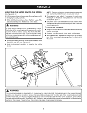
... THE STAND See Figures 8 - 9. Failure to remove the saw mounting assembly, which could cause serious personal injury. n Lift the saw and bracket assembly, allowing the assembly to tilt slightly toward you , lift the front part of the assembly to make sure the curved front edge of the... position and adjust, if necessary, to disengage from the front rail of the stand. 16 17 1 2 11 10 23 Fig. 8 WARNING: The mounting brackets are securely seated over the front rail before seating the other end of this warning may result in position, then securely tighten the four nuts...
... THE STAND See Figures 8 - 9. Failure to remove the saw mounting assembly, which could cause serious personal injury. n Lift the saw and bracket assembly, allowing the assembly to tilt slightly toward you , lift the front part of the assembly to make sure the curved front edge of the... position and adjust, if necessary, to disengage from the front rail of the stand. 16 17 1 2 11 10 23 Fig. 8 WARNING: The mounting brackets are securely seated over the front rail before seating the other end of this warning may result in position, then securely tighten the four nuts...
English Manual
Page 12
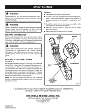
... from the rails when the levers are designed to fit snugly over both rails, the bracket adjustment screws needs to remove the saw mounting bracket assemblies (part no. A000220601), call Ryobi customer service at any other parts may create a hazard or cause product damage. GENERAL MAINTENANCE Avoid using solvents when cleaning plastic parts...
... from the rails when the levers are designed to fit snugly over both rails, the bracket adjustment screws needs to remove the saw mounting bracket assemblies (part no. A000220601), call Ryobi customer service at any other parts may create a hazard or cause product damage. GENERAL MAINTENANCE Avoid using solvents when cleaning plastic parts...
Repair Sheet
Page 3
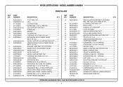
KEY NOS. 30-34 AND 36-47 2 LOCKING LEVER END CAP 1 RIGHT CAM 1 HANDLE, M.S. MAY BE PURCHASED LOCALLY 3 MODEL NUMBER A18MS01 PARTS LIST KEY NO. 1 2 3 4 5 6 7 8 9 10 11 12 13 14 15 16 17 18 19 20 21 22 23 24 25 26 27 28 PART NUMBER ... MOUNTING BRACKET 1 SCALE (MEASURING TAPE 2 SAW MOUNTING BRACKET END CAP 2 PIN (D5 X 45 mm 2 SAW MOUNTING BRACKET CARRYING HANDLE 1 * SCREW (M6 X 18 mm PAN HD 2 * SCREW (M6 X 30 mm PAN HD 1 * HEX NUT (M6 1 REAR CLAMPING JAW PROTECTOR 1 REAR CLAMING JAW 1 FRONT CLAMPING JAW 1 SCREW A (PAN HD. - SPECIAL 2 SCREW B (PAN HD. - RYOBI MITER STAND...
KEY NOS. 30-34 AND 36-47 2 LOCKING LEVER END CAP 1 RIGHT CAM 1 HANDLE, M.S. MAY BE PURCHASED LOCALLY 3 MODEL NUMBER A18MS01 PARTS LIST KEY NO. 1 2 3 4 5 6 7 8 9 10 11 12 13 14 15 16 17 18 19 20 21 22 23 24 25 26 27 28 PART NUMBER ... MOUNTING BRACKET 1 SCALE (MEASURING TAPE 2 SAW MOUNTING BRACKET END CAP 2 PIN (D5 X 45 mm 2 SAW MOUNTING BRACKET CARRYING HANDLE 1 * SCREW (M6 X 18 mm PAN HD 2 * SCREW (M6 X 30 mm PAN HD 1 * HEX NUT (M6 1 REAR CLAMPING JAW PROTECTOR 1 REAR CLAMING JAW 1 FRONT CLAMPING JAW 1 SCREW A (PAN HD. - SPECIAL 2 SCREW B (PAN HD. - RYOBI MITER STAND...
