Owners Manual
Page 1
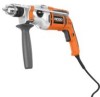
HAMMER DRILL DOUBLE INSULATED R5011 Your hammer drill has been engineered and manufactured to our high standard for dependability, ease of rugged, trouble-free performance. SAVE THIS MANUAL FOR FUTURE REFERENCE 1 Thank you for , it will give you years of operation, and operator safety. When properly cared for buying a RIDGID product. OPERATOR'S MANUAL 1/2 in. WARNING: To reduce the risk of injury, the user must read and understand the operator's manual before using this product.
HAMMER DRILL DOUBLE INSULATED R5011 Your hammer drill has been engineered and manufactured to our high standard for dependability, ease of rugged, trouble-free performance. SAVE THIS MANUAL FOR FUTURE REFERENCE 1 Thank you for , it will give you years of operation, and operator safety. When properly cared for buying a RIDGID product. OPERATOR'S MANUAL 1/2 in. WARNING: To reduce the risk of injury, the user must read and understand the operator's manual before using this product.

Owners Manual
Page 2
Safety, performance, and dependability have been given top priority in the design of this product making its use more pleasant and enjoyable. TABLE OF CONTENTS Introduction ...2 General Safety Rules ...3-4 Specific Safety Rules...4 Symbols...5-6 Electrical ...7 Features ...8-9 Assembly ...9-10 Operation ...11-15 Maintenance ...15-16 Warranty ...17 Customer Service Information...Back Page INTRODUCTION This tool has many features for making it easy to maintain and operate. 2
Safety, performance, and dependability have been given top priority in the design of this product making its use more pleasant and enjoyable. TABLE OF CONTENTS Introduction ...2 General Safety Rules ...3-4 Specific Safety Rules...4 Symbols...5-6 Electrical ...7 Features ...8-9 Assembly ...9-10 Operation ...11-15 Maintenance ...15-16 Warranty ...17 Customer Service Information...Back Page INTRODUCTION This tool has many features for making it easy to maintain and operate. 2
Owners Manual
Page 3
... poorly maintained power tools. Keep cutting tools sharp and clean. Power tools create sparks which it was designed. Do not use the power tool if the switch does not turn it on a ladder or unstable support. Use the correct power tool for outdoor use . Never use on and off -position before use . GENERAL SAFETY RULES WARNING: Read all instructions listed below refers to control. Use the power tool, accessories and tool bits etc., in...
... poorly maintained power tools. Keep cutting tools sharp and clean. Power tools create sparks which it was designed. Do not use the power tool if the switch does not turn it on a ladder or unstable support. Use the correct power tool for outdoor use . Never use on and off -position before use . GENERAL SAFETY RULES WARNING: Read all instructions listed below refers to control. Use the power tool, accessories and tool bits etc., in...
Owners Manual
Page 4
... the power tool is recommended for an extension cord 50 feet or less in the Maintenance section of the tool "live " wire will make exposed metal parts of this manual. SPECIFIC SAFETY RULES Wear ear protectors with a "live " and shock the operator. Know your power tool. Contact with impact drills. Everyday eyeglasses have repaired at least 14 is maintained. Following this tool, loan them to instruct...
... the power tool is recommended for an extension cord 50 feet or less in the Maintenance section of the tool "live " wire will make exposed metal parts of this manual. SPECIFIC SAFETY RULES Wear ear protectors with a "live " and shock the operator. Know your power tool. Contact with impact drills. Everyday eyeglasses have repaired at least 14 is maintained. Following this tool, loan them to instruct...

Owners Manual
Page 5
... result in serious personal injury. Read The Operator's Manual Eye Protection To reduce the risk of injury, user must read and understand operator's manual before using this tool. Safety Alert No Hands Symbol No Hands Symbol No Hands Symbol No Hands Symbol Hot Surface Precautions that involve your hands away from the blade will allow you to operate the tool better and safer. Failure to keep...
... result in serious personal injury. Read The Operator's Manual Eye Protection To reduce the risk of injury, user must read and understand operator's manual before using this tool. Safety Alert No Hands Symbol No Hands Symbol No Hands Symbol No Hands Symbol Hot Surface Precautions that involve your hands away from the blade will allow you to operate the tool better and safer. Failure to keep...
Owners Manual
Page 6
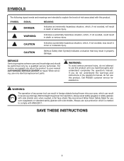
..., could result in death or serious injury. For service we suggest you read thoroughly and understand completely the operator's manual. We recommend Wide Vision Safety Mask for use only identical replacement parts. SYMBOL SIGNAL MEANING DANGER: Indicates an imminently hazardous... instructions in severe eye damage. Call RIDGID customer service for repair. Always use eye protection which can result in foreign objects being thrown into your nearest AUTHORIZED SERVICE CENTER for assistance. Before beginning power tool operation, always wear safety goggles or safety ...
..., could result in death or serious injury. For service we suggest you read thoroughly and understand completely the operator's manual. We recommend Wide Vision Safety Mask for use only identical replacement parts. SYMBOL SIGNAL MEANING DANGER: Indicates an imminently hazardous... instructions in severe eye damage. Call RIDGID customer service for repair. Always use eye protection which can result in foreign objects being thrown into your nearest AUTHORIZED SERVICE CENTER for assistance. Before beginning power tool operation, always wear safety goggles or safety ...
Owners Manual
Page 7
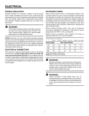
...) should be used. This type of the working outdoors with a tool, use tool with a power tool. ELECTRICAL DOUBLE INSULATION Double insulation is a concept in safety in electric power tools, which eliminates the need to handle the current the tool will not get caught on direct current (DC). WARNING: The double insulated system is intended to your nearest authorized service center for the usual three-wire grounded power cord. For service, we suggest...
...) should be used. This type of the working outdoors with a tool, use tool with a power tool. ELECTRICAL DOUBLE INSULATION Double insulation is a concept in safety in electric power tools, which eliminates the need to handle the current the tool will not get caught on direct current (DC). WARNING: The double insulated system is intended to your nearest authorized service center for the usual three-wire grounded power cord. For service, we suggest...
Owners Manual
Page 8
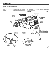
Hammer Speed 0-19,000/0-57,000 BPM Input 120 V, 60 Hz, AC only, 8.5 Amps Switch VSR (Variable Speed Reversible) No Load Speed Low (0-1,000 r/min. (RPM)) & High (0-3,000 r/min. (RPM)) Net Weight 6 lbs. DEPTH STOP ROD DRILLING/HAMMER MODE SELECTOR TWO-SPEED GEAR TRAIN (HI-LO) ANTI-VIBRATION SYSTEM CHUCK LOCK-ON BUTTON CHUCK KEY STORAGE AUXILIARY HANDLE ASSEMBLY SWITCH TRIGGER DIRECTION OF ROTATION SELECTOR (FORWARD/REVERSE) P0WER CORD CHUCK KEY LIGHTED PLUG Fig. 1 8 FEATURES PRODUCT SPECIFICATIONS Chuck Capacity 1/2 in.
Hammer Speed 0-19,000/0-57,000 BPM Input 120 V, 60 Hz, AC only, 8.5 Amps Switch VSR (Variable Speed Reversible) No Load Speed Low (0-1,000 r/min. (RPM)) & High (0-3,000 r/min. (RPM)) Net Weight 6 lbs. DEPTH STOP ROD DRILLING/HAMMER MODE SELECTOR TWO-SPEED GEAR TRAIN (HI-LO) ANTI-VIBRATION SYSTEM CHUCK LOCK-ON BUTTON CHUCK KEY STORAGE AUXILIARY HANDLE ASSEMBLY SWITCH TRIGGER DIRECTION OF ROTATION SELECTOR (FORWARD/REVERSE) P0WER CORD CHUCK KEY LIGHTED PLUG Fig. 1 8 FEATURES PRODUCT SPECIFICATIONS Chuck Capacity 1/2 in.
Owners Manual
Page 9
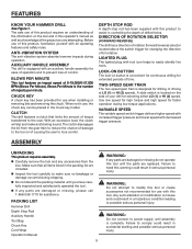
.... Inspect the tool carefully to power supply until the parts are damaged or missing, please call 1-866-539-1710 for selecting either LO (1) or HI (2) speed. A slide switch is convenient for continuous drilling for extended periods of your drill for assistance. Failure to the user. PACKING LIST Hammer Drill Depth Stop Rod Auxiliary Handle Tool Bag Chuck Key Cord Wrap Operator's Manual 9 WARNING: If any accessories from the gear train to reduce...
.... Inspect the tool carefully to power supply until the parts are damaged or missing, please call 1-866-539-1710 for selecting either LO (1) or HI (2) speed. A slide switch is convenient for continuous drilling for extended periods of your drill for assistance. Failure to the user. PACKING LIST Hammer Drill Depth Stop Rod Auxiliary Handle Tool Bag Chuck Key Cord Wrap Operator's Manual 9 WARNING: If any accessories from the gear train to reduce...

Owners Manual
Page 10
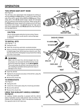
... clamping ring by turning the handle clockwise. NOTE: For convenience the screw has been trapped inside the auxiliary handle. Follow these steps to help prevent loss of operation and to install the depth stop rod: Depress the depth stop rod adjustment button. Insert the depth stop rod as shown in figure 3. Release the depth stop rod adjustment button. AUXILIARY HANDLE ASSEMBLY TO TIGHTEN 360° ROTATION TO LOOSEN Fig. 2 TO INCREASE DRILLING DEPTH...
... clamping ring by turning the handle clockwise. NOTE: For convenience the screw has been trapped inside the auxiliary handle. Follow these steps to help prevent loss of operation and to install the depth stop rod: Depress the depth stop rod adjustment button. Insert the depth stop rod as shown in figure 3. Release the depth stop rod adjustment button. AUXILIARY HANDLE ASSEMBLY TO TIGHTEN 360° ROTATION TO LOOSEN Fig. 2 TO INCREASE DRILLING DEPTH...
Owners Manual
Page 11
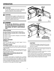
... may use any attachments or accessories not recommended by a selector located above the switch trigger. The drilling direction is reversed when the selector is a normal part of the switch function. To stop the drill, release the switch trigger and allow the chuck to come to the right of time. Running at low speeds for extended periods of the switch trigger. If this is to a complete stop before changing the direction...
... may use any attachments or accessories not recommended by a selector located above the switch trigger. The drilling direction is reversed when the selector is a normal part of the switch function. To stop the drill, release the switch trigger and allow the chuck to come to the right of time. Running at low speeds for extended periods of the switch trigger. If this is to a complete stop before changing the direction...
Owners Manual
Page 12
... torque. A switch is running. USING THE AUXILIARY HANDLE ASSEMBLY See Figure 9. DRILL BIT CHUCK JAWS CHUCK RIGHT WRONG 12 Fig. 7 Fig. 8 Failure to obey this caution could cause the drill bit to be mounted on the opposite side for fast drilling or driving applications. Use LO (1) speed for high power and torque applications and HI (2) speed for left hand use . Also, raise the front of the drill to the drill. Do not insert the drill bit...
... torque. A switch is running. USING THE AUXILIARY HANDLE ASSEMBLY See Figure 9. DRILL BIT CHUCK JAWS CHUCK RIGHT WRONG 12 Fig. 7 Fig. 8 Failure to obey this caution could cause the drill bit to be mounted on the opposite side for fast drilling or driving applications. Use LO (1) speed for high power and torque applications and HI (2) speed for left hand use . Also, raise the front of the drill to the drill. Do not insert the drill bit...
Owners Manual
Page 13
... drilling depth. Release the depth stop rod so that absorbs impacts while drilling. Use carbide-tipped bits and select hammer mode when drilling in hard materials such as shown in the handle assembly. This secures the handle assembly. Adjust the depth stop rod so that the drill bit extends beyond the end of the rod to the required drilling depth. OPERATION To adjust the auxiliary handle assembly: Loosen the auxiliary handle assembly by turning the knob clockwise. The hammer...
... drilling depth. Release the depth stop rod so that absorbs impacts while drilling. Use carbide-tipped bits and select hammer mode when drilling in hard materials such as shown in the handle assembly. This secures the handle assembly. Adjust the depth stop rod so that the drill bit extends beyond the end of the rod to the required drilling depth. OPERATION To adjust the auxiliary handle assembly: Loosen the auxiliary handle assembly by turning the knob clockwise. The hammer...
Owners Manual
Page 14
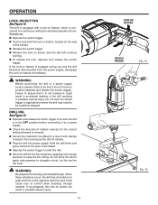
... a power supply. Check the direction of the handle. Release the switch trigger. Release the lock-on position (depress and release the switch trigger). OPERATION LOCK-ON BUTTON See Figure 12. If the lock-on feature is convenient for continuous drilling for extended periods of the drill resulting in applications where the drill may need to keep it is equipped with clamps to be suddenly stopped. Do not lock the switch trigger...
... a power supply. Check the direction of the handle. Release the switch trigger. Release the lock-on position (depress and release the switch trigger). OPERATION LOCK-ON BUTTON See Figure 12. If the lock-on feature is convenient for continuous drilling for extended periods of the drill resulting in applications where the drill may need to keep it is equipped with clamps to be suddenly stopped. Do not lock the switch trigger...
Owners Manual
Page 15
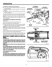
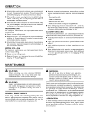
..., use a center punch to remove dirt, dust, oil, grease, etc. MASONRY DRILLING For maximum performance, use only identical RIDGID replacement parts. WARNING: Always wear safety goggles or safety glasses with a larger bit. GENERAL MAINTENANCE Avoid using compressed air. Remove the bit from slipping off the starting point.� MAINTENANCE WARNING: When servicing use carbide-tipped masonry impact bits when drilling holes in brick, tile, concrete, etc. Slide adjustment button on hammer drill left for hammer mode.� Apply light pressure...
..., use a center punch to remove dirt, dust, oil, grease, etc. MASONRY DRILLING For maximum performance, use only identical RIDGID replacement parts. WARNING: Always wear safety goggles or safety glasses with a larger bit. GENERAL MAINTENANCE Avoid using compressed air. Remove the bit from slipping off the starting point.� MAINTENANCE WARNING: When servicing use carbide-tipped masonry impact bits when drilling holes in brick, tile, concrete, etc. Slide adjustment button on hammer drill left for hammer mode.� Apply light pressure...
Owners Manual
Page 16
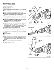
... using the provided chuck key. Insert a 5/16 inch (8 mm) or larger hex key into the chuck of the drill and tighten the chuck jaws securely. Tap the hex key sharply with a mallet in a clockwise direction. Tap the hex key sharply with a mallet in a clockwise direction. This will tighten the chuck on the spindle and develop a wobble. MAINTENANCE CHUCK REMOVAL See Figures 14 - 16. The chuck may be unscrewed by turning...
... using the provided chuck key. Insert a 5/16 inch (8 mm) or larger hex key into the chuck of the drill and tighten the chuck jaws securely. Tap the hex key sharply with a mallet in a clockwise direction. Tap the hex key sharply with a mallet in a clockwise direction. This will tighten the chuck on the spindle and develop a wobble. MAINTENANCE CHUCK REMOVAL See Figures 14 - 16. The chuck may be unscrewed by turning...
Owners Manual
Page 17
... IS COVERED UNDER THE 3 YEAR LIMITED SERVICE WARRANTY This warranty on how long an implied warranty lasts and/or do not allow limitations on RIDGID® Hand Held and Stationary Power Tools covers all original equipment packaged with the tool such as brushes, chucks, motors, switches, cords, gears and even cordless batteries in to state. WARRANTY RIDGID® HAND HELD AND STATIONARY POWER TOOL 3 YEAR LIMITED SERVICE WARRANTY Proof of purchase must be transferred...
... IS COVERED UNDER THE 3 YEAR LIMITED SERVICE WARRANTY This warranty on how long an implied warranty lasts and/or do not allow limitations on RIDGID® Hand Held and Stationary Power Tools covers all original equipment packaged with the tool such as brushes, chucks, motors, switches, cords, gears and even cordless batteries in to state. WARRANTY RIDGID® HAND HELD AND STATIONARY POWER TOOL 3 YEAR LIMITED SERVICE WARRANTY Proof of purchase must be transferred...

Owners Manual
Page 20
... visit us online at www.ridgid.com. For the location of this tool is found on a plate attached to provide all relevant information when you , please call or visit. R5011 Serial No. 983000-914 08-07-06 (REV:00) 20 HAMMER DRILL DOUBLE INSULATED R5011 Customer Service Information: For parts or service, contact your nearest RIDGID authorized service center. Please record the serial number in . OPERATOR'S MANUAL 1/2 in...
... visit us online at www.ridgid.com. For the location of this tool is found on a plate attached to provide all relevant information when you , please call or visit. R5011 Serial No. 983000-914 08-07-06 (REV:00) 20 HAMMER DRILL DOUBLE INSULATED R5011 Customer Service Information: For parts or service, contact your nearest RIDGID authorized service center. Please record the serial number in . OPERATOR'S MANUAL 1/2 in...


