Owners Manual
Page 1
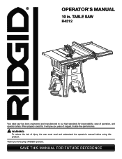
OPERATOR'S MANUAL 10 in. TABLE SAW R4512 45 Your table saw has been engineered and manufactured to our high standards for buying a RIDGID® product. WARNING: To reduce the risk of operation, and operator safety. Thank you years of rugged, trouble-free performance. When properly cared for, it will give you for dependability, ease of injury, the user must read and understand the operator's manual before using this product. SAVE THIS MANUAL FOR FUTURE REFERENCE
OPERATOR'S MANUAL 10 in. TABLE SAW R4512 45 Your table saw has been engineered and manufactured to our high standards for buying a RIDGID® product. WARNING: To reduce the risk of operation, and operator safety. Thank you years of rugged, trouble-free performance. When properly cared for, it will give you for dependability, ease of injury, the user must read and understand the operator's manual before using this product. SAVE THIS MANUAL FOR FUTURE REFERENCE
Owners Manual
Page 3
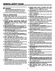
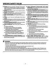
... it comes to operate tool. DON'T OVERREACH. Form habit of moving parts. Do not use , before turning it on the saw 's applications and limitations as well as the specific potential hazards related to see that keys and adjusting wrenches are rated for alignment of moving parts, ...
... it comes to operate tool. DON'T OVERREACH. Form habit of moving parts. Do not use , before turning it on the saw 's applications and limitations as well as the specific potential hazards related to see that keys and adjusting wrenches are rated for alignment of moving parts, ...
Owners Manual
Page 4
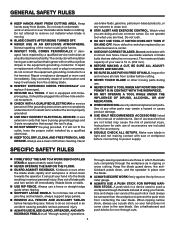
... EXPLOSIVE ATMOSPHERE. If damaged, have 3-prong grounding plugs and 3-pole receptacles that are those in which the blade cuts completely through -sawing" operations. Repair or replace a damaged or worn cord immediately. Always use a fence or straight edge guide when ripping. ...the influence of personal injury. Have defective switches replaced by a qualified service technician at approximately waist height. NEVER OPERATE THE SAw ON THE FLOOR. GUARD AGAINST KICKBACK. Stay out of the motor could ignite fumes. Inspect TOOL CORDS periodically....
... EXPLOSIVE ATMOSPHERE. If damaged, have 3-prong grounding plugs and 3-pole receptacles that are those in which the blade cuts completely through -sawing" operations. Repair or replace a damaged or worn cord immediately. Always use a fence or straight edge guide when ripping. ...the influence of personal injury. Have defective switches replaced by a qualified service technician at approximately waist height. NEVER OPERATE THE SAw ON THE FLOOR. GUARD AGAINST KICKBACK. Stay out of the motor could ignite fumes. Inspect TOOL CORDS periodically....
Owners Manual
Page 5
... does not have a straight edge to guide along the fence. IF THE POWER SUPPLY CORD IS DAMAGED, it is pushed all through sawing. Instructions for wide or long work pieces. AVOID KICKBACKS (work thrown back toward you loan someone this manual or addendums. Use of...work and that no obstructions will interfere with approved safety equipment, such as cutoff gauge when cross cutting. NEVER attempt to the saw blade guard and spreader/riving knife for every operation for any operation freehand. To reduce your exposure to these exposures varies, depending on ...
... does not have a straight edge to guide along the fence. IF THE POWER SUPPLY CORD IS DAMAGED, it is pushed all through sawing. Instructions for wide or long work pieces. AVOID KICKBACKS (work thrown back toward you loan someone this manual or addendums. Use of...work and that no obstructions will interfere with approved safety equipment, such as cutoff gauge when cross cutting. NEVER attempt to the saw blade guard and spreader/riving knife for every operation for any operation freehand. To reduce your exposure to these exposures varies, depending on ...
Owners Manual
Page 8
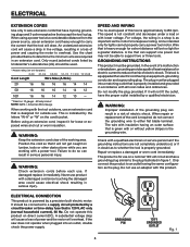
... lights cannot properly carry a power tool motor. WARNING: Improper installation of the grounding plug can result in doubt as the motor's horsepower rating. If the saw does not operate when plugged into a matching outlet that is 120 V, AC only (normal household current), 60 Hz. WARNING: Keep the extension cord clear of...
... lights cannot properly carry a power tool motor. WARNING: Improper installation of the grounding plug can result in doubt as the motor's horsepower rating. If the saw does not operate when plugged into a matching outlet that is 120 V, AC only (normal household current), 60 Hz. WARNING: Keep the extension cord clear of...
Owners Manual
Page 9
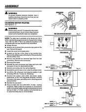
... risk of serious personal injury, never connect plug to power source until all assembly steps are not certain that secure the rear panel of the saw . Remove the 6 screws that it is connected to its lowest point. Located on the top of the junction box then lift... This is an optional procedure to change motor voltage from the wire connectors. Use the following procedures to be completed after the saw has been fully assembled. Unplug the saw . Remove the phillips screw at least a 15 amp capacity and protected by a 15 amp time-delay fuse or circuit breaker...
... risk of serious personal injury, never connect plug to power source until all assembly steps are not certain that secure the rear panel of the saw . Remove the 6 screws that it is connected to its lowest point. Located on the top of the junction box then lift... This is an optional procedure to change motor voltage from the wire connectors. Use the following procedures to be completed after the saw has been fully assembled. Unplug the saw . Remove the phillips screw at least a 15 amp capacity and protected by a 15 amp time-delay fuse or circuit breaker...
Owners Manual
Page 10
...), used to feed the workpiece over , under, behind, or in reference to the workpiece, that has hardened. Riving Knife/Spreader/Splitter (table saws) A metal piece, slightly thinner than at either end of the workpiece. Bevel Cut A cutting operation made at 90°. Cross Cut A ... A non-through the thickness of the workpiece. Kickback A hazard that serves as a guide for narrow ripping operations. Push Blocks (for table saws) Devices used for drilling large holes accurately. Gum A sticky, sap-based residue from the workpiece. Leading End The end of the blade. This...
...), used to feed the workpiece over , under, behind, or in reference to the workpiece, that has hardened. Riving Knife/Spreader/Splitter (table saws) A metal piece, slightly thinner than at either end of the workpiece. Bevel Cut A cutting operation made at 90°. Cross Cut A ... A non-through the thickness of the workpiece. Kickback A hazard that serves as a guide for narrow ripping operations. Push Blocks (for table saws) Devices used for drilling large holes accurately. Gum A sticky, sap-based residue from the workpiece. Leading End The end of the blade. This...
Owners Manual
Page 12
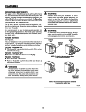
... exact angle for a cross cut , with adjustable stops at 90° and 45°. WARNING: Do not use blades rated less than the saw blade, which the workpiece is below the front rail. MITER GAUGE - The miter gauge rides in the OFF position, remove the switch key from...and prevent kickback. HEIGHT ADJUSTING HANDWHEEL/ HEIGHT LOCK KNOB - The height adusting handwheel, located on the tool and in the through sawing, or "down over the saw table, the table extensions give the operator additional support when cutting wide workpieces. The height lock knob locks the height setting of ...
... exact angle for a cross cut , with adjustable stops at 90° and 45°. WARNING: Do not use blades rated less than the saw blade, which the workpiece is below the front rail. MITER GAUGE - The miter gauge rides in the OFF position, remove the switch key from...and prevent kickback. HEIGHT ADJUSTING HANDWHEEL/ HEIGHT LOCK KNOB - The height adusting handwheel, located on the tool and in the through sawing, or "down over the saw table, the table extensions give the operator additional support when cutting wide workpieces. The height lock knob locks the height setting of ...
Owners Manual
Page 13
...with the blade before plugging tool into the switch, lift the switch button to be removed to turn off ( O ) and remove the key. This saw : Press the switch button down to remove the switch key. WARNING: ALWAYS make sure the switch is equipped with a handwheel on the ... safe place. It is not in the Operation section of this warning may cause the workpiece to turn the switch off ( O ). TO TURN YOUR SAW ON: With the switch key inserted into the power source. Fig. 6 13 TO lock your workpiece is very important to position work for...
...with the blade before plugging tool into the switch, lift the switch button to be removed to turn off ( O ) and remove the key. This saw : Press the switch button down to remove the switch key. WARNING: ALWAYS make sure the switch is equipped with a handwheel on the ... safe place. It is not in the Operation section of this warning may cause the workpiece to turn the switch off ( O ). TO TURN YOUR SAW ON: With the switch key inserted into the power source. Fig. 6 13 TO lock your workpiece is very important to position work for...
Owners Manual
Page 15
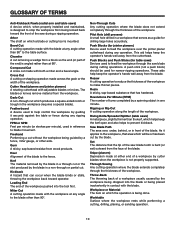
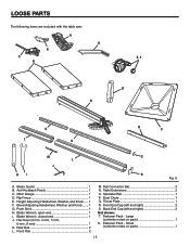
LOOSE PARTS The following items are included with the table saw: A G B C E, F N Q D K L K O P M S L J HI R Fig. 8 A. Push Stick 1 H. Rail Connector Bar 3 N. Throat Plate 1 R. Hex Keys (3 mm, 4 mm, 5 mm, 6 mm, 8 mm 1 K. Anti-Kickback Pawls 1 C. Height Adjusting Handwheel, Washer, and Knob...... 1 F. ...
LOOSE PARTS The following items are included with the table saw: A G B C E, F N Q D K L K O P M S L J HI R Fig. 8 A. Push Stick 1 H. Rail Connector Bar 3 N. Throat Plate 1 R. Hex Keys (3 mm, 4 mm, 5 mm, 6 mm, 8 mm 1 K. Anti-Kickback Pawls 1 C. Height Adjusting Handwheel, Washer, and Knob...... 1 F. ...
Owners Manual
Page 17
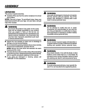
...for use this product if any parts are already assembled to the supplied leg stand. 17 WARNING: To avoid serious personal injury, never operate the saw if it , check for assistance. Failure to comply could result in a hazardous condition leading to modify this tool or create accessories not recommended for... injury. To avoid back injury, keep your back, and get help when needed. ASSEMBLY UNPACKING This product requires assembly. Carefully lift the saw from between the saw's housing and the motor. The saw is misuse and could result in serious personal injury.
...for use this product if any parts are already assembled to the supplied leg stand. 17 WARNING: To avoid serious personal injury, never operate the saw if it , check for assistance. Failure to comply could result in a hazardous condition leading to modify this tool or create accessories not recommended for... injury. To avoid back injury, keep your back, and get help when needed. ASSEMBLY UNPACKING This product requires assembly. Carefully lift the saw from between the saw's housing and the motor. The saw is misuse and could result in serious personal injury.
Owners Manual
Page 18
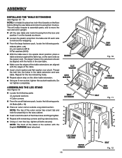
... Outer corners From the small fastener pack, locate the following parts: 6 Bolts (M10 x 25) 6 Lock washers (M10) 6 Flat washers (M10) With the table saw table. Repeat for assembly to remove the wrapping. From the large fastener pack, locate the following parts: 24 Bolts (M6 x 10) Place an... the table top, on the same side as shown. Loosen the plastic wrap from the box and position it upright. Lift the saw table and motor housing from the table and lift each of the stand is helpful to place two inch-thick boards on the boards as...
... Outer corners From the small fastener pack, locate the following parts: 6 Bolts (M10 x 25) 6 Lock washers (M10) 6 Flat washers (M10) With the table saw table. Repeat for assembly to remove the wrapping. From the large fastener pack, locate the following parts: 24 Bolts (M6 x 10) Place an... the table top, on the same side as shown. Loosen the plastic wrap from the box and position it upright. Lift the saw table and motor housing from the table and lift each of the stand is helpful to place two inch-thick boards on the boards as...

Owners Manual
Page 19
... nut. Attach the center support to heed this warning could result in the axle center piece and thread the nut over the bolt. Clean saw and the registration ridges should align with the grooves. Place the assembled leg stand over each bolt. Thread a bolt into each nut. ...cabinet regularly. NOTE: Make sure the foam block has been removed before installing the dust chute. Place the dust chute on top of the saw dust from the rear and front axle assemblies. Slide the bolt through the holes and placing the nut over the bolt. NOTE: Use a 13 mm...
... nut. Attach the center support to heed this warning could result in the axle center piece and thread the nut over the bolt. Clean saw and the registration ridges should align with the grooves. Place the assembled leg stand over each bolt. Thread a bolt into each nut. ...cabinet regularly. NOTE: Make sure the foam block has been removed before installing the dust chute. Place the dust chute on top of the saw dust from the rear and front axle assemblies. Slide the bolt through the holes and placing the nut over the bolt. NOTE: Use a 13 mm...
Owners Manual
Page 20
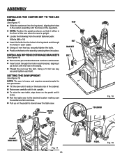
...; Locate the following from each bracket. Insert a bolt through the hole in each bracket, aligning it rests on the back side of the saw when the saw . ASSEMBLY INSTALLING THE CASTER SET TO THE LEG STAND See Figure 17. Slide the caster set into the leg stand, aligning the holes... the holes in the stand. Thread the nut over the bolt. CASTER SET feet NUT BRACKET BOLT Fig. 18 to slowly lower the table saw is firm and level. Pull up on the pedal to lower Socket head BOLT Fig. 17 20 PEDAL Fig. 19 Using a 5 mm hex key...
...; Locate the following from each bracket. Insert a bolt through the hole in each bracket, aligning it rests on the back side of the saw when the saw . ASSEMBLY INSTALLING THE CASTER SET TO THE LEG STAND See Figure 17. Slide the caster set into the leg stand, aligning the holes... the holes in the stand. Thread the nut over the bolt. CASTER SET feet NUT BRACKET BOLT Fig. 18 to slowly lower the table saw is firm and level. Pull up on the pedal to lower Socket head BOLT Fig. 17 20 PEDAL Fig. 19 Using a 5 mm hex key...

Owners Manual
Page 21
...bolt. INSTALlING the BEVEL ADJUSTING HANDWHEEL See Figure 21. Slide the bevel adjusting handwheel over the bolt on the front of the saw . bolt bolt HEIGHT ADJUSTING HANDWHEEL WASHER knob BLADE AND WRENCH storage Fig. 20 knob WASHER BEVEL ADJUSTING HANDWHEEL knob Fig. 21 miter ... 21 ACCESSORY STORAGE See Figure 22. The push stick contains a magnet. The miter gauge may be stored by sliding it is located on the saw . Slide the washer over the bolt. Screw the knob securely onto the bolt. ASSEMBLY INSTALLING the HEIGHT ADJUSTING HANDWHEEL See...
...bolt. INSTALlING the BEVEL ADJUSTING HANDWHEEL See Figure 21. Slide the bevel adjusting handwheel over the bolt on the front of the saw . bolt bolt HEIGHT ADJUSTING HANDWHEEL WASHER knob BLADE AND WRENCH storage Fig. 20 knob WASHER BEVEL ADJUSTING HANDWHEEL knob Fig. 21 miter ... 21 ACCESSORY STORAGE See Figure 22. The push stick contains a magnet. The miter gauge may be stored by sliding it is located on the saw . Slide the washer over the bolt. Screw the knob securely onto the bolt. ASSEMBLY INSTALLING the HEIGHT ADJUSTING HANDWHEEL See...
Owners Manual
Page 22
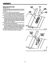
... blade nut over the hex nut. throat plate blade arbor OPEN END blade WRENCH blade blade washer blade nut Fig. 23 closed end of the saw blade and install the throat plate. Be sure the dome side of the machine. Twist the knob counterclockwise to remove it. Remove the blade... arbor. Place the new blade on the arbor shaft (blade teeth must point down toward the front of the saw to make sure it turns freely. Lower the saw in the storage area. Holding both wrenches firmly, push the closed end wrench to the back of the blade washer faces...
... blade nut over the hex nut. throat plate blade arbor OPEN END blade WRENCH blade blade washer blade nut Fig. 23 closed end of the saw blade and install the throat plate. Be sure the dome side of the machine. Twist the knob counterclockwise to remove it. Remove the blade... arbor. Place the new blade on the arbor shaft (blade teeth must point down toward the front of the saw to make sure it turns freely. Lower the saw in the storage area. Holding both wrenches firmly, push the closed end wrench to the back of the blade washer faces...
Owners Manual
Page 23
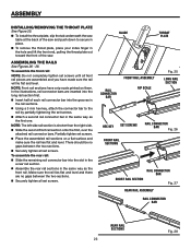
... the throat plate, place your index finger in the hole and lift the front end, pulling the throat plate out toward the front of the saw. To assemble the front rail: NOTE: Do not completely tighten set screws until all front rail pieces are no gaps between the two sections. ... connector bars. ASSEMBLY INSTALLING/REMOVing the THROAT PLATE See Figure 25. To install the throat plate, slip the tab underneath the saw table at the back of the saw and push down to the rail by partially tightening the set screws. Attach a second rail connector bar in the same way...
... the throat plate, place your index finger in the hole and lift the front end, pulling the throat plate out toward the front of the saw. To assemble the front rail: NOTE: Do not completely tighten set screws until all front rail pieces are no gaps between the two sections. ... connector bars. ASSEMBLY INSTALLING/REMOVing the THROAT PLATE See Figure 25. To install the throat plate, slip the tab underneath the saw table at the back of the saw and push down to the rail by partially tightening the set screws. Attach a second rail connector bar in the same way...
Owners Manual
Page 24
... M8 x 30 bolt, one M8 x 20 bolt, and four of the nuts will be an equal gap between the saw table and the bottom of the rip fence from the large fastener pack: 9 Hex head bolts (M8 x 30 for...for the front rail, 6 for the rail. With the rip fence lying on top of the saw table, check to see that the rip fence slides freely across the table and table extension and will not...61550; Turn the height adjusting handwheel clockwise to the front and rear rails. ASSEMBLY installing the rAILS onto the saw table See Figures 29 - 32. Take the following from the front to back of the rip ...
... M8 x 30 bolt, one M8 x 20 bolt, and four of the nuts will be an equal gap between the saw table and the bottom of the rip fence from the large fastener pack: 9 Hex head bolts (M8 x 30 for...for the front rail, 6 for the rail. With the rip fence lying on top of the saw table, check to see that the rip fence slides freely across the table and table extension and will not...61550; Turn the height adjusting handwheel clockwise to the front and rear rails. ASSEMBLY installing the rAILS onto the saw table See Figures 29 - 32. Take the following from the front to back of the rip ...
Owners Manual
Page 25
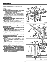
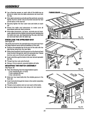
.... 33 switch assembly Fig. 34 25 INSTALLING THE SPreader BAR See Figure 33. The bolts and nuts for the spreader bar were removed from the saw table. Slide a hex head bolt into the groove on the front rail and insert the bolt through the holes in the switch assembly mounting...
.... 33 switch assembly Fig. 34 25 INSTALLING THE SPreader BAR See Figure 33. The bolts and nuts for the spreader bar were removed from the saw table. Slide a hex head bolt into the groove on the front rail and insert the bolt through the holes in the switch assembly mounting...
Owners Manual
Page 26
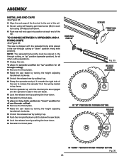
...lever by pulling it up " position (spreader position), for non-through cutting, or "up . Grasp the spreader and pull it is above the saw blade. Lock the release lever by pushing the lever down. Reinstall the throat plate. To place in spreader position (or "up" ...position for all other cutting operations. Unplug the saw. REAR RAIL end cap SCREWS Front rail end cap Fig. 35 release lever (UNLOCKED) in "UP" POSITION for through cutting release lever (LOCKED) in ...
...lever by pulling it up " position (spreader position), for non-through cutting, or "up . Grasp the spreader and pull it is above the saw blade. Lock the release lever by pushing the lever down. Reinstall the throat plate. To place in spreader position (or "up" ...position for all other cutting operations. Unplug the saw. REAR RAIL end cap SCREWS Front rail end cap Fig. 35 release lever (UNLOCKED) in "UP" POSITION for through cutting release lever (LOCKED) in ...


