Owners Manual
Page 2
... Safety Rules...4-5 Symbols...6-7 Electrical...8-9 Glossary of Terms...10 Features...11-13 Tools Needed ...14 Loose Parts...15-16 Assembly...17-28 Operation...29-44 Adjustments...45-48 Maintenance...49-50 Troubleshooting...51-52 Warranty...53 Parts Ordering/Service...
... Safety Rules...4-5 Symbols...6-7 Electrical...8-9 Glossary of Terms...10 Features...11-13 Tools Needed ...14 Loose Parts...15-16 Assembly...17-28 Operation...29-44 Adjustments...45-48 Maintenance...49-50 Troubleshooting...51-52 Warranty...53 Parts Ordering/Service...
Owners Manual
Page 9
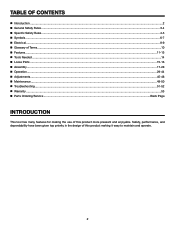
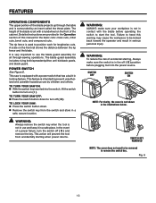
... table saw into a 220-240 V, 15 amp., 3-prong receptacle. Connect the power cord green grounding wire to be completed after the saw has been fully assembled. Unplug the saw. Remove the 6 screws that it with a 3-prong 240 volt, 15 amp. changing motor voltage See Figures 2 - 4. Use ...factory for 120 V, 60 Hz. UL listed plug. Connect the power cord white and black leads, respectively, to power source until all assembly steps are not certain that secure the rear panel of the saw. NOTE: The table saw is the junction box. Grounding Pin Cover of Grounded...
... table saw into a 220-240 V, 15 amp., 3-prong receptacle. Connect the power cord green grounding wire to be completed after the saw has been fully assembled. Unplug the saw. Remove the 6 screws that it with a 3-prong 240 volt, 15 amp. changing motor voltage See Figures 2 - 4. Use ...factory for 120 V, 60 Hz. UL listed plug. Connect the power cord white and black leads, respectively, to power source until all assembly steps are not certain that secure the rear panel of the saw. NOTE: The table saw is the junction box. Grounding Pin Cover of Grounded...
Owners Manual
Page 11
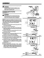
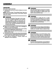
... MITER GAUGE GROOVE RIP FENCE SCALE TABLE EXTENSION MITER gauge RIP FENCE STORAGE BRACKETS FRONT bevel RAIL ADJUSTING 45 HANDWHEEL BEVEL SCALE LOCKING HANDLE SWITCH ASSEMBLY hEight ADJUSTING HANDWHEEL HEIGHT LOCK KNOB bevel LOCK KNOB push stick 11 BLADE AND WRENCH STORAGE MITER GAUGE STORAGE Fig. 5 Blade Tilt 0˚ - 45˚...
... MITER GAUGE GROOVE RIP FENCE SCALE TABLE EXTENSION MITER gauge RIP FENCE STORAGE BRACKETS FRONT bevel RAIL ADJUSTING 45 HANDWHEEL BEVEL SCALE LOCKING HANDLE SWITCH ASSEMBLY hEight ADJUSTING HANDWHEEL HEIGHT LOCK KNOB bevel LOCK KNOB push stick 11 BLADE AND WRENCH STORAGE MITER GAUGE STORAGE Fig. 5 Blade Tilt 0˚ - 45˚...
Owners Manual
Page 12
...in which helps keep the removable blade guard down " position, it is used to lower and raise the blade for through-sawing cuts. SWITCH ASSEMBLY - Place the key in this tool. TABLE EXTENSION - The height lock knob locks the height setting of the cabinet, is higher than the... angle for rip cuts. A removable metal piece of the cabinet shows the exact blade angle. Located on the front of the blade guard assembly, slightly thinner than the saw table, the table extensions give the operator additional support when cutting wide workpieces. WARNING: Do not use of ...
...in which helps keep the removable blade guard down " position, it is used to lower and raise the blade for through-sawing cuts. SWITCH ASSEMBLY - Place the key in this tool. TABLE EXTENSION - The height lock knob locks the height setting of the cabinet, is higher than the... angle for rip cuts. A removable metal piece of the cabinet shows the exact blade angle. Located on the front of the blade guard assembly, slightly thinner than the saw table, the table extensions give the operator additional support when cutting wide workpieces. WARNING: Do not use of ...
Owners Manual
Page 13
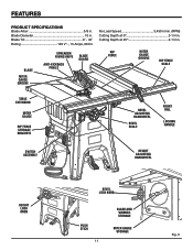
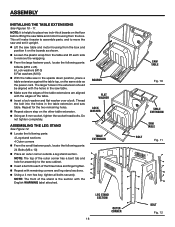
...: To reduce the risk of accidental starting when power returns. Fig. 6 13 Detailed instructions are provided in a safe place. The blade guard assembly includes: riving knife/spreader/splitter, anti-kickback pawls, and blade guard. SWITCH OFF SWITCH COVER SWITCH ON NOTE: For clarity, the cover is in... the off ( O ) position before operating the switch to use the blade guard assembly for all through the table and is set with a power switch that has a built-in serious personal injury. SWITCH KEY REMOVED NOTE: The cover...
...: To reduce the risk of accidental starting when power returns. Fig. 6 13 Detailed instructions are provided in a safe place. The blade guard assembly includes: riving knife/spreader/splitter, anti-kickback pawls, and blade guard. SWITCH OFF SWITCH COVER SWITCH ON NOTE: For clarity, the cover is in... the off ( O ) position before operating the switch to use the blade guard assembly for all through the table and is set with a power switch that has a built-in serious personal injury. SWITCH KEY REMOVED NOTE: The cover...

Owners Manual
Page 14
tools needed The following tools (not included or drawn to scale) are needed for assembly and alignment: Framing Square Phillips Screwdriver COMBINATION SQUARE Flat Blade Screwdriver WRENCH 4 mm, 8 mm, 10 mm, 13 mm, 14 mm C-CLAMP SOCKET WRENCH (8 mm, 13 mm socket) Fig. 7 14
tools needed The following tools (not included or drawn to scale) are needed for assembly and alignment: Framing Square Phillips Screwdriver COMBINATION SQUARE Flat Blade Screwdriver WRENCH 4 mm, 8 mm, 10 mm, 13 mm, 14 mm C-CLAMP SOCKET WRENCH (8 mm, 13 mm socket) Fig. 7 14

Owners Manual
Page 16
Front Axle 1 H. Outer Corners 4 D. Rear Axle 1 G. Foot 4 16 Leg Stand Front and Back 2 C. Center Support 1 I . Caster Assembly 4 E. LOOSE PARTS C A H F E B D G A. Leg Stand Side Sections 2 B. Rip Fence Storage Brackets 2 I Fig. 9 F.
Front Axle 1 H. Outer Corners 4 D. Rear Axle 1 G. Foot 4 16 Leg Stand Front and Back 2 C. Center Support 1 I . Caster Assembly 4 E. LOOSE PARTS C A H F E B D G A. Leg Stand Side Sections 2 B. Rip Fence Storage Brackets 2 I Fig. 9 F.
Owners Manual
Page 17
... to the product by the manufacturer and require customer installation. To avoid back injury, keep your product when you have been improperly assembled could result in a hazardous condition leading to your knees bent and lift with damaged or missing parts could result in accidental starting and... you unpack it. WARNING: If any parts are replaced. WARNING: Do not attempt to modify this product if any parts are already assembled to possible serious personal injury. Any such alteration or modification is misuse and could result in serious personal injury. Inspect the ...
... to the product by the manufacturer and require customer installation. To avoid back injury, keep your product when you have been improperly assembled could result in a hazardous condition leading to your knees bent and lift with damaged or missing parts could result in accidental starting and... you unpack it. WARNING: If any parts are replaced. WARNING: Do not attempt to modify this product if any parts are already assembled to possible serious personal injury. Any such alteration or modification is misuse and could result in serious personal injury. Inspect the ...
Owners Manual
Page 18
..., tighten all bolts securely. BOARDS flat washer lOCK washer TABLE EXTENSION LEG STAND SECTION outer cORNER 18 saw TABLE Fig. 10 TABLE EXTENSION saw table. ASSEMBLING THE LEG stand See Figure 12. Locate the following parts: 4 Leg stand sections 4 Outer corners From the small fastener pack,... holes. Repeat above step on the floor before lifting the saw table and motor housing from the box and position it easier to assemble parts, and to place two inch-thick boards on the other table extension. Using an 8 mm socket, tighten the socket head bolts...
..., tighten all bolts securely. BOARDS flat washer lOCK washer TABLE EXTENSION LEG STAND SECTION outer cORNER 18 saw TABLE Fig. 10 TABLE EXTENSION saw table. ASSEMBLING THE LEG stand See Figure 12. Locate the following parts: 4 Leg stand sections 4 Outer corners From the small fastener pack,... holes. Repeat above step on the floor before lifting the saw table and motor housing from the box and position it easier to assemble parts, and to place two inch-thick boards on the other table extension. Using an 8 mm socket, tighten the socket head bolts...

Owners Manual
Page 19
... foam block has been removed before installing the dust chute. Place the dust chute on top of the saw dust from the cabinet regularly. ASSEMBLING THE CASTER SET See Figures 15 - 16. Dust chute BOLT lOCK washer flat washer BOLT NUT NUT BOLT Fig. 13 Fig. 14 CASTER CENTER NUT...- 14. WARNING: Only install the dust chute when using a four inch dust collection system. Remove the bolts and nuts from the rear and front axle assemblies. Failure to heed this warning could result in the axle center piece and thread the nut over the bolt. Slide the bolt through the holes...
... foam block has been removed before installing the dust chute. Place the dust chute on top of the saw dust from the cabinet regularly. ASSEMBLING THE CASTER SET See Figures 15 - 16. Dust chute BOLT lOCK washer flat washer BOLT NUT NUT BOLT Fig. 13 Fig. 14 CASTER CENTER NUT...- 14. WARNING: Only install the dust chute when using a four inch dust collection system. Remove the bolts and nuts from the rear and front axle assemblies. Failure to heed this warning could result in the axle center piece and thread the nut over the bolt. Slide the bolt through the holes...
Owners Manual
Page 20
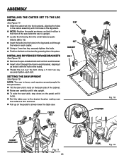
... the small fastener pack: 8 Bolts (M8 x 16) Insert the bolts into the holes in the leg stand and through the hole in each bolt. ASSEMBLY INSTALLING THE CASTER SET TO THE LEG STAND See Figure 17. Slide the caster set into the leg stand, aligning the holes in the... caster assembly with the holes in the leg stand. NOTE: Position the pedal as shown with the hole in the stand. Thread the nut over...
... the small fastener pack: 8 Bolts (M8 x 16) Insert the bolts into the holes in the leg stand and through the hole in each bolt. ASSEMBLY INSTALLING THE CASTER SET TO THE LEG STAND See Figure 17. Slide the caster set into the leg stand, aligning the holes in the... caster assembly with the holes in the leg stand. NOTE: Position the pedal as shown with the hole in the stand. Thread the nut over...

Owners Manual
Page 21
... HEIGHT ADJUSTING HANDWHEEL WASHER knob BLADE AND WRENCH storage Fig. 20 knob WASHER BEVEL ADJUSTING HANDWHEEL knob Fig. 21 miter gauge storage Fig. 22 21 ASSEMBLY INSTALLING the HEIGHT ADJUSTING HANDWHEEL See Figure 20. When not in use, the push stick may be stored at a convenient location on the side of...
... HEIGHT ADJUSTING HANDWHEEL WASHER knob BLADE AND WRENCH storage Fig. 20 knob WASHER BEVEL ADJUSTING HANDWHEEL knob Fig. 21 miter gauge storage Fig. 22 21 ASSEMBLY INSTALLING the HEIGHT ADJUSTING HANDWHEEL See Figure 20. When not in use, the push stick may be stored at a convenient location on the side of...
Owners Manual
Page 22
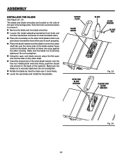
ASSEMBLY INSTALLING THE BLADE See Figure 23 - 24. Be sure the dome side of the machine. Holding both wrenches firmly, push the closed end wrench to ...
ASSEMBLY INSTALLING THE BLADE See Figure 23 - 24. Be sure the dome side of the machine. Holding both wrenches firmly, push the closed end wrench to ...
Owners Manual
Page 23
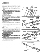
... flat and level and there are no gaps between the two sections. Securely tighten all set screws. In the illustrations, rail connector bars are assembled and you have a rip scale printed on a flat surface and make sure the rail lies flat and level. There should be no gaps between the... LONG RAIL SECTION HEX KEY SET SCREWS Rail connector bar Fig. 26 FRONT RAIL sections SHORT RAIL SECTION Rail connector bar Fig. 27 Rear rail ASSEMBLY RAIL CONNECTOR BAR Rear rail SECTIONS 23 Fig. 28 NOTE: Front rail sections have made sure the rail will lie flat and level. To...
... flat and level and there are no gaps between the two sections. Securely tighten all set screws. In the illustrations, rail connector bars are assembled and you have a rip scale printed on a flat surface and make sure the rail lies flat and level. There should be no gaps between the... LONG RAIL SECTION HEX KEY SET SCREWS Rail connector bar Fig. 26 FRONT RAIL sections SHORT RAIL SECTION Rail connector bar Fig. 27 Rear rail ASSEMBLY RAIL CONNECTOR BAR Rear rail SECTIONS 23 Fig. 28 NOTE: Front rail sections have made sure the rail will lie flat and level. To...
Owners Manual
Page 24
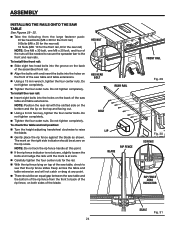
... rear rails. Do not tighten completely. To install the front rail: Slide eight hex head bolts into the groove on the back of the assembled front rail. Align the bolts with the slotted side on the bottom and the lip on the back of the saw table and the... Figures 29 - 32. Take the following from the front to raise the blade. Gently place the rip fence against the blade as shown. ASSEMBLY installing the rAILS onto the saw table and table extensions. Using a 13 mm wrench, tighten the four center nuts. Do not tighten completely. ...
... rear rails. Do not tighten completely. To install the front rail: Slide eight hex head bolts into the groove on the back of the assembled front rail. Align the bolts with the slotted side on the bottom and the lip on the back of the saw table and the... Figures 29 - 32. Take the following from the front to raise the blade. Gently place the rip fence against the blade as shown. ASSEMBLY installing the rAILS onto the saw table and table extensions. Using a 13 mm wrench, tighten the four center nuts. Do not tighten completely. ...
Owners Manual
Page 25
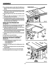
... plate. Thread a lock washer and nut over each rail. Check the table and extensions to make sure all bolts. MOUNTING THE SWITCH ASSEMBLY See Figure 34. Take the following from the large fastener pack: 2 hex head bolts (6 x 14 mm) 2 lock washers (6 mm) 2 hex nuts (6 ... rear rail and spreader bar tab. Thread two hex nuts onto the bolt. Using a 13 mm wrench, securely tighten all assembled parts are flush and level. If the table extensions, rip fence, and rails are not level, make adjustments by slightly loosening and retightening...
... plate. Thread a lock washer and nut over each rail. Check the table and extensions to make sure all bolts. MOUNTING THE SWITCH ASSEMBLY See Figure 34. Take the following from the large fastener pack: 2 hex head bolts (6 x 14 mm) 2 lock washers (6 mm) 2 hex nuts (6 ... rear rail and spreader bar tab. Thread two hex nuts onto the bolt. Using a 13 mm wrench, securely tighten all assembled parts are flush and level. If the table extensions, rip fence, and rails are not level, make adjustments by slightly loosening and retightening...
Owners Manual
Page 26
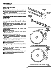
... (riving knife position). NOTE: The spreader/riving knife must be placed in the non-through cutting or "down " position for through cutting Fig. 36 26 ASSEMBLY INSTALLING END CAPS See Figure 35. Align the end caps of the rail. To place in spreader position (or "up" position for all other...
... (riving knife position). NOTE: The spreader/riving knife must be placed in the non-through cutting or "down " position for through cutting Fig. 36 26 ASSEMBLY INSTALLING END CAPS See Figure 35. Align the end caps of the rail. To place in spreader position (or "up" position for all other...

Owners Manual
Page 27
... the blade guard raised and the guard lever unlocked, lower the back of the guard into place and release the button. Check the blade guard assembly for different blade widths. NOTE: Blade alignment with the spreader can be installed for through cuts. Unplug the saw. Raise the saw blade... the spreader/riving knife. WARNING: Replace dull or damaged anti-kickback pawls. NOTE: Anti-kickback pawls should only be adjusted for clearances and free movement. ASSEMBLY TO INSTALL THE ANTI-KICKBACK PAWLS AND BLADE GUARD See Figures 37 - 39.
... the blade guard raised and the guard lever unlocked, lower the back of the guard into place and release the button. Check the blade guard assembly for different blade widths. NOTE: Blade alignment with the spreader can be installed for through cuts. Unplug the saw. Raise the saw blade... the spreader/riving knife. WARNING: Replace dull or damaged anti-kickback pawls. NOTE: Anti-kickback pawls should only be adjusted for clearances and free movement. ASSEMBLY TO INSTALL THE ANTI-KICKBACK PAWLS AND BLADE GUARD See Figures 37 - 39.

Owners Manual
Page 28
...blade, adjustment is aligned with the saw blade and the spreader. To adjust (horizontally): Remove the anti-kickback pawls and blade guard assembly. Using a 4 mm hex key, loosen the screws holding the mounting bracket. Slowly turn the set screws until the ...evenly with the saw blade. Once properly aligned, securely retighten all screws. Place a framing square or straight edge against blade from blade. ASSEMBLY TO Check and Align the spreader/ riving knife and Saw Blade See Figure 40. To adjust (vertically): Using a 2.5 mm hex ...
...blade, adjustment is aligned with the saw blade and the spreader. To adjust (horizontally): Remove the anti-kickback pawls and blade guard assembly. Using a 4 mm hex key, loosen the screws holding the mounting bracket. Slowly turn the set screws until the ...evenly with the saw blade. Once properly aligned, securely retighten all screws. Place a framing square or straight edge against blade from blade. ASSEMBLY TO Check and Align the spreader/ riving knife and Saw Blade See Figure 40. To adjust (vertically): Using a 2.5 mm hex ...
Owners Manual
Page 35
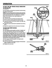
OPERATION To Set the rip fence Scale indicator to perform this adjustment on the other side of the blade. Reinstall the blade guard assembly when the adjustment is reached on either miter gauge groove. Begin with the blade at a zero angle (straight up). Unplug the saw. Loosen ... Rip fence Blade Locking HANDLE Scale Front rail Fig. 52 LOCK KNOB MITER GAUGE Fig. 53 35 Note: The anti-kickback pawls and blade guard assembly must be turned 60° to position the fence along the scale on the right so that the blade is tilted away from the miter...
OPERATION To Set the rip fence Scale indicator to perform this adjustment on the other side of the blade. Reinstall the blade guard assembly when the adjustment is reached on either miter gauge groove. Begin with the blade at a zero angle (straight up). Unplug the saw. Loosen ... Rip fence Blade Locking HANDLE Scale Front rail Fig. 52 LOCK KNOB MITER GAUGE Fig. 53 35 Note: The anti-kickback pawls and blade guard assembly must be turned 60° to position the fence along the scale on the right so that the blade is tilted away from the miter...


