

Operation Manual
Page 1
WARNING: To reduce the risk of operation, and operator safety. Thank you years of rugged, trouble-free performance. OPERATOR'S MANUAL 10 in. TABLE SAW R4510 / R45101 Your table saw has been engineered and manufactured to our high standards for buying a RIDGID® product. SAVE THIS MANUAL FOR FUTURE REFERENCE When properly cared for, it will give you for dependability, ease of injury, the user must read and understand the operator's manual before using this product.
WARNING: To reduce the risk of operation, and operator safety. Thank you years of rugged, trouble-free performance. OPERATOR'S MANUAL 10 in. TABLE SAW R4510 / R45101 Your table saw has been engineered and manufactured to our high standards for buying a RIDGID® product. SAVE THIS MANUAL FOR FUTURE REFERENCE When properly cared for, it will give you for dependability, ease of injury, the user must read and understand the operator's manual before using this product.
Operation Manual
Page 3
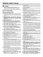
...DON'T FORCE TOOL. These cords are removed from blades. READ ALL INSTRUCTIONS READ ALL INSTRUCTIONS KNOW YOUR POWER TOOL. Learn the saw while it was not designed for lubricating and changing accessories. DISCONNECT TOOLS. Don't force the tool or attachment to hold work area...cord 25 feet or less in operation. DO NOT USE IN DANGEROUS ENVIRONMENTS. A guard or other part that it on the saw 's applications and limitations as well as the specific potential hazards related to determine that is unintentionally contacted. CHECK DAMAGED PARTS. ...
...DON'T FORCE TOOL. These cords are removed from blades. READ ALL INSTRUCTIONS READ ALL INSTRUCTIONS KNOW YOUR POWER TOOL. Learn the saw while it was not designed for lubricating and changing accessories. DISCONNECT TOOLS. Don't force the tool or attachment to hold work area...cord 25 feet or less in operation. DO NOT USE IN DANGEROUS ENVIRONMENTS. A guard or other part that it on the saw 's applications and limitations as well as the specific potential hazards related to determine that is unintentionally contacted. CHECK DAMAGED PARTS. ...
Operation Manual
Page 4
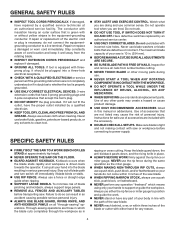
... push stick, push block, or featherboard. NEVER perform any solvents to whether the tool is equipped with saw or workpiece before transporting saw is driven back towards the operator. Make sure blade is the equipment-grounding conductor. GENERAL SAFETY RULES INSPECT...; DO NOT MODIFY the plug provided. Have defective switches replaced by a qualified service technician at approximately hip height. NEVER OPERATE THE SAW ON THE FLOOR. GUARD AGAINST KICKBACK. Instructions for and remove all "through the workpiece as in . (254 mm). ...
... push stick, push block, or featherboard. NEVER perform any solvents to whether the tool is equipped with saw or workpiece before transporting saw is driven back towards the operator. Make sure blade is the equipment-grounding conductor. GENERAL SAFETY RULES INSPECT...; DO NOT MODIFY the plug provided. Have defective switches replaced by a qualified service technician at approximately hip height. NEVER OPERATE THE SAW ON THE FLOOR. GUARD AGAINST KICKBACK. Instructions for and remove all "through the workpiece as in . (254 mm). ...

Operation Manual
Page 5
...accessory. MAKE SURE THE WORK AREA HAS AMPLE LIGHTING to see the work and that are specially designed to the saw . ALWAYS TURN OFF SAW before it , to avoid accidental starting when reconnecting to power supply. ONLY USE BLADES within the thickness range ..., birth defects, or other users. Some examples of these instructions also. f) Do not perform any work that is pushed all through sawing. b) Use saw blade guard and riving knife for every operation for wide or long workpieces. AVOID KICKBACKS (work before disconnecting it is twisted ...
...accessory. MAKE SURE THE WORK AREA HAS AMPLE LIGHTING to see the work and that are specially designed to the saw . ALWAYS TURN OFF SAW before it , to avoid accidental starting when reconnecting to power supply. ONLY USE BLADES within the thickness range ..., birth defects, or other users. Some examples of these instructions also. f) Do not perform any work that is pushed all through sawing. b) Use saw blade guard and riving knife for every operation for wide or long workpieces. AVOID KICKBACKS (work before disconnecting it is twisted ...
Operation Manual
Page 7
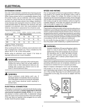
... understood, or if in doubt as to result in a risk of the working with this product. This is as important as the plug. If the saw does not operate when plugged into a matching outlet that accept the tool's plug. ELECTRICAL CONNECTION This product is for electric current to support two or...
... understood, or if in doubt as to result in a risk of the working with this product. This is as important as the plug. If the saw does not operate when plugged into a matching outlet that accept the tool's plug. ELECTRICAL CONNECTION This product is for electric current to support two or...

Operation Manual
Page 8
... rests while performing a cutting, drilling, planing, or sanding operation. 8 Kickback A hazard that has hardened. Push Blocks (for table saws) Device used to hold the workpiece during any angle to the table surface. Workpiece or Material The item on which produces a square-sided...operations. Non-Through Cuts Any cutting operation where the blade does not extend completely through the thickness of the workpiece. Through Sawing Any cutting operation where the blade extends completely through the thickness of the workpiece. The blades or knives remove material from...
... rests while performing a cutting, drilling, planing, or sanding operation. 8 Kickback A hazard that has hardened. Push Blocks (for table saws) Device used to hold the workpiece during any angle to the table surface. Workpiece or Material The item on which produces a square-sided...operations. Non-Through Cuts Any cutting operation where the blade does not extend completely through the thickness of the workpiece. Through Sawing Any cutting operation where the blade extends completely through the thickness of the workpiece. The blades or knives remove material from...

Operation Manual
Page 9
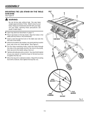
Blade Arbor 5/8 in . Cutting Depth at 90 3-1/2 in . Rating 120 V~, 15 Amps, 60 Hz No Load Speed 4,400 r/min. (RPM) RIVING KNIFE ANTI-KICKBACK PAWLS BLADE GUARD ASSEMBLY SAW BLADE MITER GAUGE RIP FENCE MICRO-ADJUST WHEEL LOCKING LEVER FRONT RAIL BLADE WRENCHES BEVEL SCALE GRIPS BLADE AND BLADE WRENCH STORAGE LEG STAND BEVEL LOCKING LEVER SWITCH ASSEMBLY BEVEL ADJUSTING HANDWHEEL BEVEL INDICATOR HEIGHT ADJUSTING KNOB BLADE HEIGHT LOCK KNOB Fig. 3 9 Cutting Depth at 45 2-1/2 in . FEATURES PRODUCT SPECIFICATIONS Blade Diameter 10 in .
Blade Arbor 5/8 in . Cutting Depth at 90 3-1/2 in . Rating 120 V~, 15 Amps, 60 Hz No Load Speed 4,400 r/min. (RPM) RIVING KNIFE ANTI-KICKBACK PAWLS BLADE GUARD ASSEMBLY SAW BLADE MITER GAUGE RIP FENCE MICRO-ADJUST WHEEL LOCKING LEVER FRONT RAIL BLADE WRENCHES BEVEL SCALE GRIPS BLADE AND BLADE WRENCH STORAGE LEG STAND BEVEL LOCKING LEVER SWITCH ASSEMBLY BEVEL ADJUSTING HANDWHEEL BEVEL INDICATOR HEIGHT ADJUSTING KNOB BLADE HEIGHT LOCK KNOB Fig. 3 9 Cutting Depth at 45 2-1/2 in . FEATURES PRODUCT SPECIFICATIONS Blade Diameter 10 in .

Operation Manual
Page 10
.... A sturdy metal fence guides the workpiece and is raised and lowered with the bevel locking lever. RIVING KNIFE - When in the non-through sawing, or "down over the blade for bevel angles. SCALE - BEVEL LOCKING LEVER - For maximum performance, it is inaccessible to children and others ...may be pulled back toward the operator. To lock the switch in a location that you with optional clamps and accessories. FEATURES KNOW YOUR TABLE SAW See Figure 3. BLADE HEIGHT LOCK KNOB - Located on the front of the blade. MITER GAUGE GROOVES - When in the center of the...
.... A sturdy metal fence guides the workpiece and is raised and lowered with the bevel locking lever. RIVING KNIFE - When in the non-through sawing, or "down over the blade for bevel angles. SCALE - BEVEL LOCKING LEVER - For maximum performance, it is inaccessible to children and others ...may be pulled back toward the operator. To lock the switch in a location that you with optional clamps and accessories. FEATURES KNOW YOUR TABLE SAW See Figure 3. BLADE HEIGHT LOCK KNOB - Located on the front of the blade. MITER GAUGE GROOVES - When in the center of the...

Operation Manual
Page 11
...prevent the tool from the switch and store in a safe, secure location. FEATURES OPERATING COMPONENTS The upper portion of the blade projects up through -sawing operations. The blade guard assembly includes: riving knife, anti-kickback pawls, and blade guard. WARNING: To reduce the risk of accidental starting when...between the rip fence and the blade. SWITCH IN LOCKED POSITION Fig. 4 11 To accommodate wide panels, the saw is used to position work for lengthwise cuts. TO LOCK YOUR SAW: Press the switch down to use and keep it in a safe place. SWITCH ON SWITCH OFF ...
...prevent the tool from the switch and store in a safe, secure location. FEATURES OPERATING COMPONENTS The upper portion of the blade projects up through -sawing operations. The blade guard assembly includes: riving knife, anti-kickback pawls, and blade guard. WARNING: To reduce the risk of accidental starting when...between the rip fence and the blade. SWITCH IN LOCKED POSITION Fig. 4 11 To accommodate wide panels, the saw is used to position work for lengthwise cuts. TO LOCK YOUR SAW: Press the switch down to use and keep it in a safe place. SWITCH ON SWITCH OFF ...

Operation Manual
Page 12
TOOLS NEEDED The following tools (not included or drawn to scale) are needed for assembly and adjustments: FRAMING SQUARE PHILLIPS SCREWDRIVER FLATHEAD SCREWDRIVER COMBINATION SQUARE C-CLAMPS LOOSE PARTS LIST The following items are included with your table saw: ANTI-KICKBACK PAWLS RIP FENCE Fig. 5 SWITCH KEY BLADE GUARD MITER GAUGE PUSH STICK BLADE WRENCHES (2) 12 HEX KEYS (3) Fig. 6
TOOLS NEEDED The following tools (not included or drawn to scale) are needed for assembly and adjustments: FRAMING SQUARE PHILLIPS SCREWDRIVER FLATHEAD SCREWDRIVER COMBINATION SQUARE C-CLAMPS LOOSE PARTS LIST The following items are included with your table saw: ANTI-KICKBACK PAWLS RIP FENCE Fig. 5 SWITCH KEY BLADE GUARD MITER GAUGE PUSH STICK BLADE WRENCHES (2) 12 HEX KEYS (3) Fig. 6

Operation Manual
Page 14
... securely. NOTE: This tool is misuse and could result in serious personal injury. If any parts are not assembled to accommodate the saw base, washers, lock washers, wing nuts, and the thickness of sufficient length to the product by the manufacturer and require customer installation... be mounted to heed this purpose. Failure to a firm supporting surface such as a workbench or leg stand. MOUNTING HOLES The table saw must be bolted securely using 1/4 in this tool until you unpack it close to specific procedures explained in . If shipping has influenced ...
... securely. NOTE: This tool is misuse and could result in serious personal injury. If any parts are not assembled to accommodate the saw base, washers, lock washers, wing nuts, and the thickness of sufficient length to the product by the manufacturer and require customer installation... be mounted to heed this purpose. Failure to a firm supporting surface such as a workbench or leg stand. MOUNTING HOLES The table saw must be bolted securely using 1/4 in this tool until you unpack it close to specific procedures explained in . If shipping has influenced ...
Operation Manual
Page 16
... Figure 9. For the three remaining holes, insert the bolts through the hole in the table saw and into the hole in back injury. Open leg stand as described on page 17. Place saw base and into the hole in the stand. Add a lock washer, flat washer, ring terminal... to your back. Align the holes in the table with your legs, not your body. Hand tighten. ASSEMBLY MOUNTING THE LEG STAND ON THE TABLE SAW BASE See Figure 9. Keep your knees bent and lift with the holes in the end braces. Insert a bolt through the hole in the...
... Figure 9. For the three remaining holes, insert the bolts through the hole in the table saw and into the hole in back injury. Open leg stand as described on page 17. Place saw base and into the hole in the stand. Add a lock washer, flat washer, ring terminal... to your back. Align the holes in the table with your legs, not your body. Hand tighten. ASSEMBLY MOUNTING THE LEG STAND ON THE TABLE SAW BASE See Figure 9. Keep your knees bent and lift with the holes in the end braces. Insert a bolt through the hole in the...

Operation Manual
Page 17
... brace locking the leg stand in an open position. ASSEMBLY TO OPEN THE LEG STAND See Figures 10 - 12 Grasp the grips on the saw table and stand it upright as shown below. Step on the release lever and pull the grips toward you at the same time. ... floor by pushing the grips toward the floor. With your hands on the grips, push the leg stand towards the ground until the table saw is in an open position.
... brace locking the leg stand in an open position. ASSEMBLY TO OPEN THE LEG STAND See Figures 10 - 12 Grasp the grips on the saw table and stand it upright as shown below. Step on the release lever and pull the grips toward you at the same time. ... floor by pushing the grips toward the floor. With your hands on the grips, push the leg stand towards the ground until the table saw is in an open position.

Operation Manual
Page 18
... leg stand no longer rocks. • Turning clockwise will lower the foot • Turning counterclockwise will raise the foot TO STORE THE TABLE SAW ACCESSORIES See Figures 14 - 15. WING NUT PUSH STICK LEVELING FOOT BLADE BLADE WRENCHES WING NUT MITER GAUGE Fig. 13 ANTI-KICKBACK PAWLS ANTI.... Loosen both the top and bottom wing nuts. Lift the saw . ASSEMBLY TO SECURE/LEVEL THE SAW See Figure 13. If the saw 's accessories. With the leg stand open and the table saw resting on either side of the saw cabinet) specifically designed for the saw rocks from side to side.
... leg stand no longer rocks. • Turning clockwise will lower the foot • Turning counterclockwise will raise the foot TO STORE THE TABLE SAW ACCESSORIES See Figures 14 - 15. WING NUT PUSH STICK LEVELING FOOT BLADE BLADE WRENCHES WING NUT MITER GAUGE Fig. 13 ANTI-KICKBACK PAWLS ANTI.... Loosen both the top and bottom wing nuts. Lift the saw . ASSEMBLY TO SECURE/LEVEL THE SAW See Figure 13. If the saw 's accessories. With the leg stand open and the table saw resting on either side of the saw cabinet) specifically designed for the saw rocks from side to side.

Operation Manual
Page 19
... grips firmly, pull the handles toward you until the release lever clicks and locks into place. ASSEMBLY TO CLOSE THE LEG STAND AND MOVE THE SAW See Figures 16 - 19. Remove any workpieces from the tool. Remove and securely store any tools or accessories such as rip fence, miter... gauge, clamps, blade guard, etc. Lower the saw until the leg stand and saw are balanced on the release lever, grasp the grips, and lift the handles up and away from the body. Push the table...
... grips firmly, pull the handles toward you until the release lever clicks and locks into place. ASSEMBLY TO CLOSE THE LEG STAND AND MOVE THE SAW See Figures 16 - 19. Remove any workpieces from the tool. Remove and securely store any tools or accessories such as rip fence, miter... gauge, clamps, blade guard, etc. Lower the saw until the leg stand and saw are balanced on the release lever, grasp the grips, and lift the handles up and away from the body. Push the table...

Operation Manual
Page 20
... push down until the back of the housing until it up " position for all non-through cutting: Remove the throat plate. Raise the saw blade by turning the height adjusting knob clockwise. Unlock the release lever by pushing the lever down . Reinstall the throat plate. 20 To...the spring-loaded riving clamp. Pull the riving knife up until the internal pins are engaged and the riving knife is level with the saw blade. Lock the release lever by pulling it up. Grasp the riving knife and pull it towards the right side of the...
... push down until the back of the housing until it up " position for all non-through cutting: Remove the throat plate. Raise the saw blade by turning the height adjusting knob clockwise. Unlock the release lever by pushing the lever down . Reinstall the throat plate. 20 To...the spring-loaded riving clamp. Pull the riving knife up until the internal pins are engaged and the riving knife is level with the saw blade. Lock the release lever by pulling it up. Grasp the riving knife and pull it towards the right side of the...

Operation Manual
Page 21
...61550; Reinstall the throat plate. TO INSTALL THE ANTI-KICKBACK PAWLS AND BLADE GUARD See Figures 23 - 24. Fig. 23 Raise the saw . BLADE WRENCH (LEFT) HANDLE ANTI-KICKBACK PAWLS BLADE GUARD BLADE WRENCH (RIGHT) SET SCREW HEX NUT BUTTON Fig. 22 GUARD LEVER WARNING: Replace...could cause damage to the left side) to the back of serious personal injury. NOTE: Arbor shaft has right-hand threads. Unplug the saw. Remove blade wrenches from storage area by turning the height/bevel adjusting handwheel clockwise. Place riving knife in "up" position....
...61550; Reinstall the throat plate. TO INSTALL THE ANTI-KICKBACK PAWLS AND BLADE GUARD See Figures 23 - 24. Fig. 23 Raise the saw . BLADE WRENCH (LEFT) HANDLE ANTI-KICKBACK PAWLS BLADE GUARD BLADE WRENCH (RIGHT) SET SCREW HEX NUT BUTTON Fig. 22 GUARD LEVER WARNING: Replace...could cause damage to the left side) to the back of serious personal injury. NOTE: Arbor shaft has right-hand threads. Unplug the saw. Remove blade wrenches from storage area by turning the height/bevel adjusting handwheel clockwise. Place riving knife in "up" position....

Operation Manual
Page 22
...against blade from blade. NOTE: Blade alignment can be adjusted for clearances and free movement. TO CHECK AND ALIGN THE RIVING KNIFE AND SAW BLADE See Figure 25. CORRECT INCORRECT SCREWS Fig. 24 VERTICAL ADJUSTMENT HORIZONTAL ADJUSTMENT 22 Fig. 25 If the blade guard is not ...height adjusting knob clockwise. Remove the anti-kickback pawls and blade guard assembly. If the riving knife is out of alignment with the saw blade. Once properly aligned, securely retighten the screws. Check again for squareness and continue to adjust if needed to align...
...against blade from blade. NOTE: Blade alignment can be adjusted for clearances and free movement. TO CHECK AND ALIGN THE RIVING KNIFE AND SAW BLADE See Figure 25. CORRECT INCORRECT SCREWS Fig. 24 VERTICAL ADJUSTMENT HORIZONTAL ADJUSTMENT 22 Fig. 25 If the blade guard is not ...height adjusting knob clockwise. Remove the anti-kickback pawls and blade guard assembly. If the riving knife is out of alignment with the saw blade. Once properly aligned, securely retighten the screws. Check again for squareness and continue to adjust if needed to align...

Operation Manual
Page 23
... and may gather. Use the right type of cut Not following : Making a cut with incorrect blade depth Sawing into knots or nails in the workpiece Twisting the wood while making a cut Failing to support work Forcing a cut ... tool for the purposes listed below: Straight line cutting operations such as the following correct operating procedures Misusing the saw without the blade guard unless specifically instructed to do so could result in serious personal injury. The use steady, even pressure. Knock ...
... and may gather. Use the right type of cut Not following : Making a cut with incorrect blade depth Sawing into knots or nails in the workpiece Twisting the wood while making a cut Failing to support work Forcing a cut ... tool for the purposes listed below: Straight line cutting operations such as the following correct operating procedures Misusing the saw without the blade guard unless specifically instructed to do so could result in serious personal injury. The use steady, even pressure. Knock ...

Operation Manual
Page 24
...workpiece, with the edge flush against the jig and against the rip fence and resting firmly on the saw table. A push block has a handle fastened by recessed screws from scrap wood and used for a ... screws. If ripping a narrow workpiece places the hands too close the gap between the rip fence and the saw table. From the back side of wood 3/4 in the side of the jig. STOP Fig. ... 28 or thinner. They can be necessary to make a jig: Attach a handle to avoid damaging the saw blade. wide, and 21 in . To use a push stick, push block, and/or featherboard so your hands ...
...workpiece, with the edge flush against the jig and against the rip fence and resting firmly on the saw table. A push block has a handle fastened by recessed screws from scrap wood and used for a ... screws. If ripping a narrow workpiece places the hands too close the gap between the rip fence and the saw table. From the back side of wood 3/4 in the side of the jig. STOP Fig. ... 28 or thinner. They can be necessary to make a jig: Attach a handle to avoid damaging the saw blade. wide, and 21 in . To use a push stick, push block, and/or featherboard so your hands ...


