

Operation Manual
Page 1
SAVE THIS MANUAL FOR FUTURE REFERENCE WARNING: To reduce the risk of operation, and operator safety. Tile SAW R4090 Your tile saw has been engineered and manufactured to our high standards for buying a RIDGID® product. Thank you years of rugged, trouble-free performance. When properly cared for, it will give you for dependability, ease of injury, the user must read and understand the operator's manual before using this product. OPERATOR'S MANUAL 10 in.
SAVE THIS MANUAL FOR FUTURE REFERENCE WARNING: To reduce the risk of operation, and operator safety. Tile SAW R4090 Your tile saw has been engineered and manufactured to our high standards for buying a RIDGID® product. Thank you years of rugged, trouble-free performance. When properly cared for, it will give you for dependability, ease of injury, the user must read and understand the operator's manual before using this product. OPERATOR'S MANUAL 10 in.

Operation Manual
Page 2
... more pleasant and enjoyable. TABLE OF CONTENTS Introduction...2 General Safety Rules...3-4 Specific Safety Rules...5 Symbols...6 Electrical...7-8 Features...9-10 Tools Needed...10 Loose Parts...11 Assembly...12-21 Operation...22-28 Adjustments...29-30 Maintenance...31-32 Warranty...33 ...
... more pleasant and enjoyable. TABLE OF CONTENTS Introduction...2 General Safety Rules...3-4 Specific Safety Rules...5 Symbols...6 Electrical...7-8 Features...9-10 Tools Needed...10 Loose Parts...11 Assembly...12-21 Operation...22-28 Adjustments...29-30 Maintenance...31-32 Warranty...33 ...
Operation Manual
Page 4
Do not reach underneath work or around or over the wheel while wheel is 10 in. (254 mm). Before making contact with incorrect size holes. If damaged, have 3-prong grounding plugs and 3-pole receptacles that are defective or incorrect. ...
Do not reach underneath work or around or over the wheel while wheel is 10 in. (254 mm). Before making contact with incorrect size holes. If damaged, have 3-prong grounding plugs and 3-pole receptacles that are defective or incorrect. ...

Operation Manual
Page 7
....0 12.1-16.0 Cord Length Wire Size (A.W.G.) 25' 16 16 16 16 14 14 50' 16 16 16 14 14 12 100' 16 16 14 12 10 - **Used on direct current (DC). This tool is for electric current to either flat blade terminal. This product is equipped with insulation having the same...
....0 12.1-16.0 Cord Length Wire Size (A.W.G.) 25' 16 16 16 16 14 14 50' 16 16 16 14 14 12 100' 16 16 14 12 10 - **Used on direct current (DC). This tool is for electric current to either flat blade terminal. This product is equipped with insulation having the same...

Operation Manual
Page 9
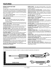
...; LEG STAND Fig. 3 9 - English Rip Capacity (tile size 34 in . Diagonal Capacity (tile size 24 in . Throat Capacity 17 in . FEATURES PRODUCT SPECIFICATIONS Wheel Diameter 10 in . Maximum Depth of Cut 3-3/4 in .
...; LEG STAND Fig. 3 9 - English Rip Capacity (tile size 34 in . Diagonal Capacity (tile size 24 in . Throat Capacity 17 in . FEATURES PRODUCT SPECIFICATIONS Wheel Diameter 10 in . Maximum Depth of Cut 3-3/4 in .
Operation Manual
Page 10
... Provides a convenient carrier to turn the laser on when the saw arm. SEDIMENT SEPARATION SYSTEM™ - Sliding table - VARIABLE FLOW VALVE - A 10 in the water tank. The bevel lock lever securely locks the saw . NEVER DRY VALVE - Adjusts the flow of this warning could result in .... located on the motor housing. The variable speed dial is recycled into the cutting wheel for assembly and alignment: phillips screwdriver FRAMING SQUARE 10 - The wheel wrench is plugged in. WARNING: Do not use of this operator's manual as well as a knowledge of the motor...
... Provides a convenient carrier to turn the laser on when the saw arm. SEDIMENT SEPARATION SYSTEM™ - Sliding table - VARIABLE FLOW VALVE - A 10 in the water tank. The bevel lock lever securely locks the saw . NEVER DRY VALVE - Adjusts the flow of this warning could result in .... located on the motor housing. The variable speed dial is recycled into the cutting wheel for assembly and alignment: phillips screwdriver FRAMING SQUARE 10 - The wheel wrench is plugged in. WARNING: Do not use of this operator's manual as well as a knowledge of the motor...

Operation Manual
Page 15
...a hose clamp. Store the nozzle in the saw arm by pushing the tube over the connector. ASSEMBLY installING water supply valve See Figure 10. Unscrew the connector from the water supply valve and remove the mounting bracket. Align holes in mounting bracket with holes ...the connector. Attach the clear tube to valves, connectors, etc. Secure with a hose clamp. nuts screws water supply valve Connector Fig. 10 Clear tube Connector divertor valve hose clamp Clear tube with cleaning nozzle Clear tube Rubber boot Water supply valve Cleaning nozzle storage Inner leg ...
...a hose clamp. Store the nozzle in the saw arm by pushing the tube over the connector. ASSEMBLY installING water supply valve See Figure 10. Unscrew the connector from the water supply valve and remove the mounting bracket. Align holes in mounting bracket with holes ...the connector. Attach the clear tube to valves, connectors, etc. Secure with a hose clamp. nuts screws water supply valve Connector Fig. 10 Clear tube Connector divertor valve hose clamp Clear tube with cleaning nozzle Clear tube Rubber boot Water supply valve Cleaning nozzle storage Inner leg ...

Operation Manual
Page 20
... guard lock counterclockwise to unlock. Pull the wheel guard open to engage with the wheel guard, while thicker wheels will not tighten properly. WARNING: A 10 in. Larger wheels will come in contact with the flats on this tool. WARNING: To prevent possible electrical hazards, have openings, grooves, or teeth on..., or teeth. ASSEMBLY tile cutting wheel For maximum performance and safety, it is recommended that have a qualified electrician check the line if you use the 10 in.
... guard lock counterclockwise to unlock. Pull the wheel guard open to engage with the wheel guard, while thicker wheels will not tighten properly. WARNING: A 10 in. Larger wheels will come in contact with the flats on this tool. WARNING: To prevent possible electrical hazards, have openings, grooves, or teeth on..., or teeth. ASSEMBLY tile cutting wheel For maximum performance and safety, it is recommended that have a qualified electrician check the line if you use the 10 in.

Repair Sheet
Page 3
... 1t 8 Tornillo (M6 x 12 mm, cab. R4090 KEY P/N 1 080009008701 2 080009008002 3 080009008003 4 080009008004 5 080009008005 6 080009008006 7 080009008007 8 080009008008 9 080009008009 10 080009008010 11 080009008011 12 080009008012 13 080009008013 14 080009008014 15...201;F. 1 080009008701 2 080009008002 3 080009008003 4 080009008004 5 080009008005 6 080009008006 7 080009008007 8 080009008008 9 080009008009 10 080009008010 11 080009008011 12 080009008012 13 080009008013 14 080009008014 15 080009008015 16 080009008016 17 080009005911 18 080009008905 19 080009008223 ...
... 1t 8 Tornillo (M6 x 12 mm, cab. R4090 KEY P/N 1 080009008701 2 080009008002 3 080009008003 4 080009008004 5 080009008005 6 080009008006 7 080009008007 8 080009008008 9 080009008009 10 080009008010 11 080009008011 12 080009008012 13 080009008013 14 080009008014 15...201;F. 1 080009008701 2 080009008002 3 080009008003 4 080009008004 5 080009008005 6 080009008006 7 080009008007 8 080009008008 9 080009008009 10 080009008010 11 080009008011 12 080009008012 13 080009008013 14 080009008014 15 080009008015 16 080009008016 17 080009005911 18 080009008905 19 080009008223 ...

Repair Sheet
Page 5
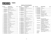
... Wiper 4 Wiper Plate 4 Screw (M4 x 8 mm, Truss Hd 8 Screw (M5 x 5 mm, Soc. R4090 PARTS LIST FOR FIGURE B KEY P/N DESCRIPTION QTY KEY P/N DESCRIPTION QTY KEY P/N DESCRIPTION QTY 1 080009008025 Screw (M5 x 10 mm, Soc. Key Nos. 34-45 1 Hex Nut (M6 1 Lock Plate 1 Screw (M5 x 15 mm...4 25 080009008019 Front Table 1 26 080009005905 No Hands Label 2 27 080009008034 Table Locking Rod 1 28 080009008035 Pin (D2 x 10 mm 1 29 080009008045 30 080009008046 31 080009008048 32 080009008047 33 080009008705 34 080009008086 35 080009008261 36 080009008262 37 080009008263 38 080009008255 39 ...
... Wiper 4 Wiper Plate 4 Screw (M4 x 8 mm, Truss Hd 8 Screw (M5 x 5 mm, Soc. R4090 PARTS LIST FOR FIGURE B KEY P/N DESCRIPTION QTY KEY P/N DESCRIPTION QTY KEY P/N DESCRIPTION QTY 1 080009008025 Screw (M5 x 10 mm, Soc. Key Nos. 34-45 1 Hex Nut (M6 1 Lock Plate 1 Screw (M5 x 15 mm...4 25 080009008019 Front Table 1 26 080009005905 No Hands Label 2 27 080009008034 Table Locking Rod 1 28 080009008035 Pin (D2 x 10 mm 1 29 080009008045 30 080009008046 31 080009008048 32 080009008047 33 080009008705 34 080009008086 35 080009008261 36 080009008262 37 080009008263 38 080009008255 39 ...

Repair Sheet
Page 9
...1 18 080009008142 Bevel Handle Grip 1 19 080009008143 Screw (M8 x 20 mm, Rd. Hd 1 20 080009008144 Bevel Handle Cap 1 21 080009008044 Screw (M5 x 10 mm, Rd. Hd 4 Handle Housing Logo Label 1 Variable Speed Control 1 Circuit Board Assembly (Variable Speed 1 Screw (M2.5 x 8 mm, Rd. Key ... 1 Lock Pin 1 O-Ring (D10.6 x D6.8 x 1.9t 1 9 Hd 4 Screw (M5 x 10 mm 2 Screw (M4 x 14 mm 16 Motor End Cap 1 Hex Nut (M4 1 Tie Mount 1 Screw (M4 x 8 mm, Rd. R4090 PARTS LIST FOR FIGURE C KEY P/N DESCRIPTION QTY KEY P/N DESCRIPTION QTY KEY P/N DESCRIPTION QTY 1 080009008095 Screw...
...1 18 080009008142 Bevel Handle Grip 1 19 080009008143 Screw (M8 x 20 mm, Rd. Hd 1 20 080009008144 Bevel Handle Cap 1 21 080009008044 Screw (M5 x 10 mm, Rd. Hd 4 Handle Housing Logo Label 1 Variable Speed Control 1 Circuit Board Assembly (Variable Speed 1 Screw (M2.5 x 8 mm, Rd. Key ... 1 Lock Pin 1 O-Ring (D10.6 x D6.8 x 1.9t 1 9 Hd 4 Screw (M5 x 10 mm 2 Screw (M4 x 14 mm 16 Motor End Cap 1 Hex Nut (M4 1 Tie Mount 1 Screw (M4 x 8 mm, Rd. R4090 PARTS LIST FOR FIGURE C KEY P/N DESCRIPTION QTY KEY P/N DESCRIPTION QTY KEY P/N DESCRIPTION QTY 1 080009008095 Screw...

Repair Sheet
Page 10
...Ring (D1.9 x ID 5.8 1 Laser Guide Button 1 Spring 1 Laser Housing 1 Nozzle Body 1 Screw (M4 x 8 mm, Rd. R4090 PARTS LIST FOR FIGURE C KEY P/N DESCRIPTION QTY KEY P/N DESCRIPTION QTY KEY P/N DESCRIPTION QTY 82 080009008132 83 080009008131 84 080009008713 85 080009008114 86 ...2RS 1 Screw (M5 x 8 mm, Flat Hd 1 Spindle Retainer 1 Spindle 1 Key 1 Reduction Gear 1 Shim (0.5 mm 1 Screw (M5 x 18 mm, Nylok 3 10 ID x 1240 mm)...... 1 Inner Guard Cover 1 Outer Blade Guard 1 Rotary Spindle 1 Wheel Nut (Spindle) (5/8 in.-18 1 Outer Washer 1 Splash Guard 1 Wheel Guard...
...Ring (D1.9 x ID 5.8 1 Laser Guide Button 1 Spring 1 Laser Housing 1 Nozzle Body 1 Screw (M4 x 8 mm, Rd. R4090 PARTS LIST FOR FIGURE C KEY P/N DESCRIPTION QTY KEY P/N DESCRIPTION QTY KEY P/N DESCRIPTION QTY 82 080009008132 83 080009008131 84 080009008713 85 080009008114 86 ...2RS 1 Screw (M5 x 8 mm, Flat Hd 1 Spindle Retainer 1 Spindle 1 Key 1 Reduction Gear 1 Shim (0.5 mm 1 Screw (M5 x 18 mm, Nylok 3 10 ID x 1240 mm)...... 1 Inner Guard Cover 1 Outer Blade Guard 1 Rotary Spindle 1 Wheel Nut (Spindle) (5/8 in.-18 1 Outer Washer 1 Splash Guard 1 Wheel Guard...
Repair Sheet
Page 16
... Nos. 36, 49 and 53-55).......... 1 Right Main Tube Assembly (Inc. Figure A, Keys 19-20 1 Operator's Manual (R4090 Pump)........ 1 Operator's Manual 1 16 Key Nos. 14-29; 4 of Key 14, 4 of Key 19 and 1 of Key 21 1... Left Support Tube Assembly (Inc. R4090 KEY P/N DESCRIPTION QTY 1 080009008707 2 080009008221 3 080009008222 4 080009008712 5 080009008216 6 987321001 7 080009005918 8 080009004912 9 080009005920 10 080009005913 11 080009006019 12 080009006004 13 080009008285 14 080009008002 15 080009008272 16 080009008273 17 080009008274...
... Nos. 36, 49 and 53-55).......... 1 Right Main Tube Assembly (Inc. Figure A, Keys 19-20 1 Operator's Manual (R4090 Pump)........ 1 Operator's Manual 1 16 Key Nos. 14-29; 4 of Key 14, 4 of Key 19 and 1 of Key 21 1... Left Support Tube Assembly (Inc. R4090 KEY P/N DESCRIPTION QTY 1 080009008707 2 080009008221 3 080009008222 4 080009008712 5 080009008216 6 987321001 7 080009005918 8 080009004912 9 080009005920 10 080009005913 11 080009006019 12 080009006004 13 080009008285 14 080009008002 15 080009008272 16 080009008273 17 080009008274...


