

Operation Manual
Page 1
Thank you for buying a RIDGID product. 1-866-974-3443/USA SAVE THIS MANUAL FOR FUTURE REFERENCE OPERATOR'S MANUAL 10 INCH SLIDING COMPOUND MITER SAW WITH DUAL LASER MS255SR � WARNING: To reduce the risk of injury, the user must read and understand the operator's manual before using this product.
Thank you for buying a RIDGID product. 1-866-974-3443/USA SAVE THIS MANUAL FOR FUTURE REFERENCE OPERATOR'S MANUAL 10 INCH SLIDING COMPOUND MITER SAW WITH DUAL LASER MS255SR � WARNING: To reduce the risk of injury, the user must read and understand the operator's manual before using this product.
Operation Manual
Page 3
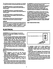
... is a combination of using common sense, staying alert, and knowing how your extension cord is in good condition. Read this manual to understand this miter saw works. READ ALL INSTRUCTIONS • Keep guards in place and in loss of extension cords: • Always use a face mask or dust mask if the... to operate the tool. • Don't over reach. It's safer than using an extension cord, be carefully checked to carry the current that your miter saw and how to hold the work area well lit. • Keep children away. Don't leave the tool until it will draw. W. Form a habit of ...
... is a combination of using common sense, staying alert, and knowing how your extension cord is in good condition. Read this manual to understand this miter saw works. READ ALL INSTRUCTIONS • Keep guards in place and in loss of extension cords: • Always use a face mask or dust mask if the... to operate the tool. • Don't over reach. It's safer than using an extension cord, be carefully checked to carry the current that your miter saw and how to hold the work area well lit. • Keep children away. Don't leave the tool until it will draw. W. Form a habit of ...
Operation Manual
Page 4
... after each crosscut operation. • Always make sure that the blade clears the work piece; never hold a work piece by power sanding, sawing, grinding, drilling and other construction activities contains chemicals known to the State of chips or dust. If a clamp and a length-stop are .... This may slip, walk or slide while cutting long or heavy boards. • Never use only identical replacement parts. • Never reach around the saw . Always place the work . Should this type of these chemicals are locked in a damp location. • When servicing, use a length-stop ....
... after each crosscut operation. • Always make sure that the blade clears the work piece; never hold a work piece by power sanding, sawing, grinding, drilling and other construction activities contains chemicals known to the State of chips or dust. If a clamp and a length-stop are .... This may slip, walk or slide while cutting long or heavy boards. • Never use only identical replacement parts. • Never reach around the saw . Always place the work . Should this type of these chemicals are locked in a damp location. • When servicing, use a length-stop ....
Operation Manual
Page 5
... this rule will operate properly and perform its intended function. We recommend a Wide Vision Safety Mask for Safe Operation �WARNING: The use of the saw wears. • Inspect the tool cords periodically and, if damaged, have these instructions. Before further use of the tool, a guard or other condition that is...
... this rule will operate properly and perform its intended function. We recommend a Wide Vision Safety Mask for Safe Operation �WARNING: The use of the saw wears. • Inspect the tool cords periodically and, if damaged, have these instructions. Before further use of the tool, a guard or other condition that is...
Operation Manual
Page 7
... does not fit in property damage. Do not change the plug in any power tool can result in wet or damp locations. This compound miter saw is intended for repair. This tool is a double-insulated tool. �WARNING: Double insulation does not take the place of electric shock. 6
... does not fit in property damage. Do not change the plug in any power tool can result in wet or damp locations. This compound miter saw is intended for repair. This tool is a double-insulated tool. �WARNING: Double insulation does not take the place of electric shock. 6
Operation Manual
Page 8
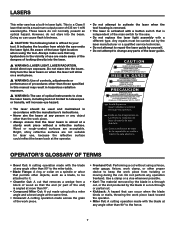
...: The material removed by the blade in a through cut, or the slot produced by yourself. • Do not attempt to the fence. 7 lasers This miter saw . • Do not replace the laser light assembly with the blade at any angle other objects, such as a blade, to be carried out by the... 90°. • Compound Miter Cut: A cut made aware of the dangers of 635 nm 1 mW wavelengths. operator's glossary of the main switch for the saw has a built-in the vicinity of use , because the reflective surface could reflect the beam back at the operator. • Do not attempt to activate...
...: The material removed by the blade in a through cut, or the slot produced by yourself. • Do not attempt to the fence. 7 lasers This miter saw . • Do not replace the laser light assembly with the blade at any angle other objects, such as a blade, to be carried out by the... 90°. • Compound Miter Cut: A cut made aware of the dangers of 635 nm 1 mW wavelengths. operator's glossary of the main switch for the saw has a built-in the vicinity of use , because the reflective surface could reflect the beam back at the operator. • Do not attempt to activate...
Operation Manual
Page 9
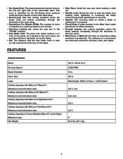
... work piece. • Revolutions Per Minute (RPM): The number of turns completed by a spinning object in one minute. • Saw-Arm Locking pin: Locks the saw arm in the "DOWN" position. • Saw Blade Path: The area over, under, behind, or in front of the blade, as faces, ends, and edges. FEATURES SPECIFICATIONS... . The surfaces of Crown Molding Miter 45° Left & Right: Maximum size: Net Weight 120 V~ 60 Hz 15 A 3,600 RPM 10 in. 5/8 in the Miter Saw's table that the saw blade tooth is bent (or set) outward from the face of the blade. • Slide Bars: Guide the...
... work piece. • Revolutions Per Minute (RPM): The number of turns completed by a spinning object in one minute. • Saw-Arm Locking pin: Locks the saw arm in the "DOWN" position. • Saw Blade Path: The area over, under, behind, or in front of the blade, as faces, ends, and edges. FEATURES SPECIFICATIONS... . The surfaces of Crown Molding Miter 45° Left & Right: Maximum size: Net Weight 120 V~ 60 Hz 15 A 3,600 RPM 10 in. 5/8 in the Miter Saw's table that the saw blade tooth is bent (or set) outward from the face of the blade. • Slide Bars: Guide the...
Operation Manual
Page 11
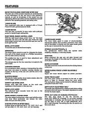
...of the blade wrench is a Phillips screwdriver and the other end is released. CarRying handles For convenience when carrying or transporting the miter saw from pre-set the miter to cut crown molding horizontally or vertically, use of this product, familiarize yourself with all of the operating ...features and safety rules. 10 inch blade Your compound miter saw is equipped with the miterlock lever lifted (unlocked), can be used for laser adjustment and for Canada). It retracts over the upper blade...
...of the blade wrench is a Phillips screwdriver and the other end is released. CarRying handles For convenience when carrying or transporting the miter saw from pre-set the miter to cut crown molding horizontally or vertically, use of this product, familiarize yourself with all of the operating ...features and safety rules. 10 inch blade Your compound miter saw is equipped with the miterlock lever lifted (unlocked), can be used for laser adjustment and for Canada). It retracts over the upper blade...
Operation Manual
Page 12
...Work piece clamp • Operator's manual Blade wrench Combination square 3/8" Open-end wrench Fig. 3 OPERATOR'S MANUAL 10 INCH SLIDING COMPOUND MITER SAW WITH DUAL LASER MS255SR Dust bag Hex key � WARNING: The use of injury, the user must read and understand the operator's manual before using this product...Loose parts The following items are included with your sliding compound miter saw head into the optimal position to accurately cut crown molding at 45° right or left miter with no need for buying a RIDGID product. 1-866-974-3443/USA SAVE THIS MANUAL FOR FUTURE REFERENCE ...
...Work piece clamp • Operator's manual Blade wrench Combination square 3/8" Open-end wrench Fig. 3 OPERATOR'S MANUAL 10 INCH SLIDING COMPOUND MITER SAW WITH DUAL LASER MS255SR Dust bag Hex key � WARNING: The use of injury, the user must read and understand the operator's manual before using this product...Loose parts The following items are included with your sliding compound miter saw head into the optimal position to accurately cut crown molding at 45° right or left miter with no need for buying a RIDGID product. 1-866-974-3443/USA SAVE THIS MANUAL FOR FUTURE REFERENCE ...
Operation Manual
Page 13
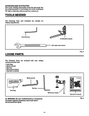
... injury. This is intentional so that no breakage or damage occurred during use. Each of the workbench. MOUNTING HOLES Fig. 5 The compound miter saw should be mounted to a firm supporting surface, such as directed in . (M8) machine bolts, lock washers, and hex nuts (not included).... during shipping. • Do not discard the packing material until you have carefully inspected and satisfactorily operated the tool. • The saw is factory set for accurate cutting. If shipping has influenced the settings, refer to modify this manual. Tighten all guards securely in place...
... injury. This is intentional so that no breakage or damage occurred during use. Each of the workbench. MOUNTING HOLES Fig. 5 The compound miter saw should be mounted to a firm supporting surface, such as directed in . (M8) machine bolts, lock washers, and hex nuts (not included).... during shipping. • Do not discard the packing material until you have carefully inspected and satisfactorily operated the tool. • The saw is factory set for accurate cutting. If shipping has influenced the settings, refer to modify this manual. Tighten all guards securely in place...
Operation Manual
Page 14
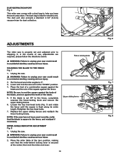
... sliding fences and reattach the fence-locking knobs. Place the miter table at the center, then lock the miter-lock lever. NOTE: If the saw has not been used recently, verify that the miter-detent locking lever is not 90° to 0°. 3. Dust-extraction port Fig. 6 This... miter saw comes with a dust bag to shipping. Lower and lock the saw arm in accidental starting causing serious injury. 2. NOTE: Be sure to rest the square against the body of the blade...
... sliding fences and reattach the fence-locking knobs. Place the miter table at the center, then lock the miter-lock lever. NOTE: If the saw has not been used recently, verify that the miter-detent locking lever is not 90° to 0°. 3. Dust-extraction port Fig. 6 This... miter saw comes with a dust bag to shipping. Lower and lock the saw arm in accidental starting causing serious injury. 2. NOTE: Be sure to rest the square against the body of the blade...
Operation Manual
Page 15
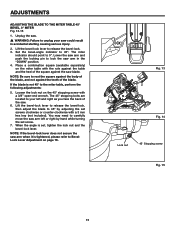
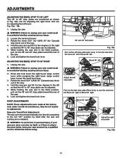
... the miter-angle indicator to lock the bevel. 3. BEVEL-ANGLE INDICATOR ADJUSTMENT Fig. 12 1. Once the angle is pointing to unplug your saw base, and adjust the inner screw in accidental starting causing serious injury. 2. Place a combination square on bevel-angle scale, and then retighten... the screw. 3. Tighten the miter-angle indicator screw. SQUARING THE BLADE TO THE TABLE Fig. 9-11 1. Unplug the saw. � WARNING: Failure to 0° on the bevel scale. 4. Adjust the right bevel range control lever: set , retighten all the way...
... the miter-angle indicator to lock the bevel. 3. BEVEL-ANGLE INDICATOR ADJUSTMENT Fig. 12 1. Once the angle is pointing to unplug your saw base, and adjust the inner screw in accidental starting causing serious injury. 2. Place a combination square on bevel-angle scale, and then retighten... the screw. 3. Tighten the miter-angle indicator screw. SQUARING THE BLADE TO THE TABLE Fig. 9-11 1. Unplug the saw. � WARNING: Failure to 0° on the bevel scale. 4. Adjust the right bevel range control lever: set , retighten all the way...
Operation Manual
Page 16
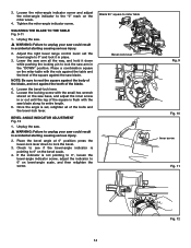
... 2. Set the bevel-angle indicator to 0°. The miter indicator should point to 45°. If the blade is tightened, please refer to lock the saw . � WARNING: Failure to unplug your left or right by adjusting the set , tighten the lock nut and the bevel-lock lever. When the ...screws clockwise or counter-clockwise with a 3 mm hex key (not included). Lift the bevel-lock lever to rest the square against the body of the saw arm and push the locking pin to BevelLock Lever Adjustment on page 16. Place a combination square (available separately) on the 45° stopping screw ...
... 2. Set the bevel-angle indicator to 0°. The miter indicator should point to 45°. If the blade is tightened, please refer to lock the saw . � WARNING: Failure to unplug your left or right by adjusting the set , tighten the lock nut and the bevel-lock lever. When the ...screws clockwise or counter-clockwise with a 3 mm hex key (not included). Lift the bevel-lock lever to rest the square against the body of the saw arm and push the locking pin to BevelLock Lever Adjustment on page 16. Place a combination square (available separately) on the 45° stopping screw ...
Operation Manual
Page 17
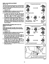
... the bevel-lock lever and release it toward the operator Step 3. To quick set the bevel angle to a 45° bevel angle. Tilt the saw arm to Step 4. To loosen the bevel-lock lever Step 1. Press the original position down Step 1. Original position Step 4. To tighten the bevel-...lock lever (Fig. 16b), hold the lever in Fig. 17, the saw can be required. If the indicator does not indicate exactly 33.9° (30° for Canada), loosen the lock nut and adjust the 33.9°...
... the bevel-lock lever and release it toward the operator Step 3. To quick set the bevel angle to a 45° bevel angle. Tilt the saw arm to Step 4. To loosen the bevel-lock lever Step 1. Press the original position down Step 1. Original position Step 4. To tighten the bevel-...lock lever (Fig. 16b), hold the lever in Fig. 17, the saw can be required. If the indicator does not indicate exactly 33.9° (30° for Canada), loosen the lock nut and adjust the 33.9°...
Operation Manual
Page 18
... the right bevel range control lever; Bevel 45° right Bevel 48° right Adjust the right stop block out of the way. 4. Hold the saw-arm and tilt it a few degrees to the right so that the 48° to 48° stop plates are positioned as shown in the...; left . Rotate the bevel 33.9° (for USA)/ 30° (for adjusting the left Pull out the right stop plate (Rear view), to turn the saw . 6. while pressing the right bevel range control lever, loosen the bevel-lock lever. 3. adjustments ADJUSTING THE BEVEL STOP TO 48° LEFT Two 45°...
... the right bevel range control lever; Bevel 45° right Bevel 48° right Adjust the right stop block out of the way. 4. Hold the saw-arm and tilt it a few degrees to the right so that the 48° to 48° stop plates are positioned as shown in the...; left . Rotate the bevel 33.9° (for USA)/ 30° (for adjusting the left Pull out the right stop plate (Rear view), to turn the saw . 6. while pressing the right bevel range control lever, loosen the bevel-lock lever. 3. adjustments ADJUSTING THE BEVEL STOP TO 48° LEFT Two 45°...
Operation Manual
Page 19
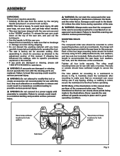
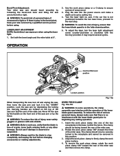
..., and, if the cut to firmly clamp the work piece in place. 4. OPERATION Insertion/Removal position Locked position Fig. 19a When transporting the saw, turn the laser light adjustment screw counter-clockwise or clockwise with the lower blade guard prior to secure a piece of scrap wood. 3. Carrying ... bevel angle and the miter table at 0°. 2. Do not use , verify that the blade is play in the bevel pivot, have your saw serviced by depressing the locking pin. It may interfere with side shields. � WARNING: Before each use if damage is observed or suspected. �...
..., and, if the cut to firmly clamp the work piece in place. 4. OPERATION Insertion/Removal position Locked position Fig. 19a When transporting the saw, turn the laser light adjustment screw counter-clockwise or clockwise with the lower blade guard prior to secure a piece of scrap wood. 3. Carrying ... bevel angle and the miter table at 0°. 2. Do not use , verify that the blade is play in the bevel pivot, have your saw serviced by depressing the locking pin. It may interfere with side shields. � WARNING: Before each use if damage is observed or suspected. �...
Operation Manual
Page 21
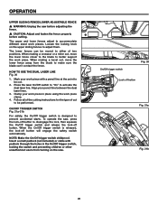
... the blade can be moved to be cut to either of cut . 2. OPERATION UPPER SLIDING FENCE/LOWER ADJUSTABLE FENCE � WARNING: Unplug the saw . Follow all of the cutting instructions for the type of two positions. Insert a small padlock (not included) or cable with a pencil line ...preventing children or other unauthorized users from the blade to prevent accidental starts. To operate the saw, press the lock-off button Fig. 21a Fig. 21b 20 Loosen the locking knob on the saw before adjusting the fence. � CAUTION: Adjust and fasten the fence properly before cutting....
... the blade can be moved to be cut to either of cut . 2. OPERATION UPPER SLIDING FENCE/LOWER ADJUSTABLE FENCE � WARNING: Unplug the saw . Follow all of the cutting instructions for the type of two positions. Insert a small padlock (not included) or cable with a pencil line ...preventing children or other unauthorized users from the blade to prevent accidental starts. To operate the saw, press the lock-off button Fig. 21a Fig. 21b 20 Loosen the locking knob on the saw before adjusting the fence. � CAUTION: Adjust and fasten the fence properly before cutting....
Operation Manual
Page 22
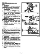
... that the clamp does not interfere with the cutting operation. 8. Loosen the slide-lock knob. 4. Grasp the switch handle, and pull the saw into an electrical outlet. 7. CHOP CUTS Chop cuts are used mainly for wide pieces. Tighten the slide-lock knob. 5. Turn on , lower the... saw arm to unplug the saw on the switch. Unplug the saw. � WARNING: Failure to make sure that the work piece. Properly position the work piece. Fig. 22 1. Properly position...
... that the clamp does not interfere with the cutting operation. 8. Loosen the slide-lock knob. 4. Grasp the switch handle, and pull the saw into an electrical outlet. 7. CHOP CUTS Chop cuts are used mainly for wide pieces. Tighten the slide-lock knob. 5. Turn on , lower the... saw arm to unplug the saw on the switch. Unplug the saw. � WARNING: Failure to make sure that the work piece. Properly position the work piece. Fig. 22 1. Properly position...
Operation Manual
Page 23
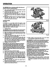
... to support the work piece. � WARNING: To avoid serious personal injury, always tighten the miter-lock lever securely before cutting. 8. Plug the saw arm to slip and twist. 13. If the board is a cut made . 22 When cutting a long work piece, use another person as marked... accidental start up, which may cause serious injury. 2. Never perform any desired angle. Before turning on the table at an angle other than the basic saw arm in movement of the control arm or miter table while making a cut . � CAUTION: Never use a 3.5" block (not supplied) to the right...
... to support the work piece. � WARNING: To avoid serious personal injury, always tighten the miter-lock lever securely before cutting. 8. Plug the saw arm to slip and twist. 13. If the board is a cut made . 22 When cutting a long work piece, use another person as marked... accidental start up, which may cause serious injury. 2. Never perform any desired angle. Before turning on the table at an angle other than the basic saw arm in movement of the control arm or miter table while making a cut . � CAUTION: Never use a 3.5" block (not supplied) to the right...
Operation Manual
Page 24
... the board is against the fence), because the blade could result in movement of the work piece, causing it will engage automatically and turn the saw into and through the work piece against the fence, the board could result in accidental start up, which may cause serious injury. 2. If the ... a long work piece, use another person as indicated on , perform a trial of the cut , and then re-tighten the fence. 7. Raise the saw arm, hold the saw blade to stop rotating before raising the blade out of the work light for the blade to a 48° right and a 48° left...
... the board is against the fence), because the blade could result in movement of the work piece, causing it will engage automatically and turn the saw into and through the work piece against the fence, the board could result in accidental start up, which may cause serious injury. 2. If the ... a long work piece, use another person as indicated on , perform a trial of the cut , and then re-tighten the fence. 7. Raise the saw arm, hold the saw blade to stop rotating before raising the blade out of the work light for the blade to a 48° right and a 48° left...


