

Operation Manual
Page 2
table of contents General Safety Instructions 2 Specific Safety Instructions 3 Additional Instructions for Safe Operation 4 Symbols 5 Electrical 6 Lasers 7 Glossary 7 Features 8 Tools Needed 11 Loose Parts 11 Assembly 12 Adjustments 13 Operation 18 Maintenance 31 Troubleshooting 33 Warranty 34
table of contents General Safety Instructions 2 Specific Safety Instructions 3 Additional Instructions for Safe Operation 4 Symbols 5 Electrical 6 Lasers 7 Glossary 7 Features 8 Tools Needed 11 Loose Parts 11 Assembly 12 Adjustments 13 Operation 18 Maintenance 31 Troubleshooting 33 Warranty 34
Operation Manual
Page 8
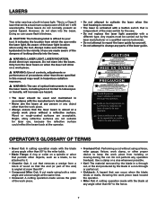
...• Always ensure that can cause flash blindness. � CAUTION: The following label is independent of looking directly into the laser. � WARNING: LASER LIGHT. Be aware of the laser light location when using a fence, miter gauge, fixture, work piece. • Freehand Cut: Performing a cut that removes ...90° to the miter table. • Blade Flange: A ring or collar on a work piece. � WARNING: Use of controls, adjustments or performance of procedures other than 90° to your tool. Use a clamp or a vise whenever possible. • Kerf: The material removed...
...• Always ensure that can cause flash blindness. � CAUTION: The following label is independent of looking directly into the laser. � WARNING: LASER LIGHT. Be aware of the laser light location when using a fence, miter gauge, fixture, work piece. • Freehand Cut: Performing a cut that removes ...90° to the miter table. • Blade Flange: A ring or collar on a work piece. � WARNING: Use of controls, adjustments or performance of procedures other than 90° to your tool. Use a clamp or a vise whenever possible. • Kerf: The material removed...
Operation Manual
Page 10
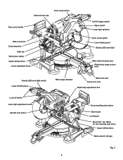
...carry handle Rear carry handle Slide-lock knob Dust extraction Slide bar Work piece clamp Upper sliding fence Lower adjustable fence On/Off trigger switch Upper guard Laser light aperture Arbor screw guard Lower blade guard Gravity LED work light Miter-detent locking lever Right bevel ...range control lever Gravity LED work light switch Laser On/Off switch Lock-off button Laser light adjustment screw Spindle-lock button Miter angle indicator Miter-lock lever Bevel-lock lever Depth stop adjustment bolt Crown molding stop button Bevel scale Locking pin Bevel 33.9&#...
...carry handle Rear carry handle Slide-lock knob Dust extraction Slide bar Work piece clamp Upper sliding fence Lower adjustable fence On/Off trigger switch Upper guard Laser light aperture Arbor screw guard Lower blade guard Gravity LED work light Miter-detent locking lever Right bevel ...range control lever Gravity LED work light switch Laser On/Off switch Lock-off button Laser light adjustment screw Spindle-lock button Miter angle indicator Miter-lock lever Bevel-lock lever Depth stop adjustment bolt Crown molding stop button Bevel scale Locking pin Bevel 33.9&#...
Operation Manual
Page 11
...a Phillips screwdriver and the other end is a hex key. Upper Sliding Fence/ Lower ADJUSTABLE Fence Upper and lower fences adjust for Canada). The work -piece widths. The depth adjustment is used for laser adjustment and for changing the blade. FEATURES KNOW YOUR SLIDING COMPOUND MITER SAW The safe use of.... Gravity LED Work Light Unique work piece clamp is a feature used with sufficient power to limit the blade depth. Depth-stop adjustment BOLT The depth-stop adjustment is mounted on the top of the slide bar. BEVEL 33.9° (USA)/ 30° (CANADA) STOP BLOCK Use this...
...a Phillips screwdriver and the other end is a hex key. Upper Sliding Fence/ Lower ADJUSTABLE Fence Upper and lower fences adjust for Canada). The work -piece widths. The depth adjustment is used for laser adjustment and for changing the blade. FEATURES KNOW YOUR SLIDING COMPOUND MITER SAW The safe use of.... Gravity LED Work Light Unique work piece clamp is a feature used with sufficient power to limit the blade depth. Depth-stop adjustment BOLT The depth-stop adjustment is mounted on the top of the slide bar. BEVEL 33.9° (USA)/ 30° (CANADA) STOP BLOCK Use this...
Operation Manual
Page 12
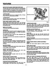
...position to accurately cut . Tools needed The following tools (not included) are needed for making adjustments: 3mm Hex key Loose parts The following items are included with no need for buying a RIDGID product. 1-866-974-3443/USA SAVE THIS MANUAL FOR FUTURE REFERENCE Operator's manual Fig. 4...; Operator's manual Blade wrench Combination square 3/8" Open-end wrench Fig. 3 OPERATOR'S MANUAL 10 INCH SLIDING COMPOUND MITER SAW WITH DUAL LASER MS255SR Dust bag Hex key � WARNING: The use of injury, the user must read and understand the operator's manual before using this product.
...position to accurately cut . Tools needed The following tools (not included) are needed for making adjustments: 3mm Hex key Loose parts The following items are included with no need for buying a RIDGID product. 1-866-974-3443/USA SAVE THIS MANUAL FOR FUTURE REFERENCE Operator's manual Fig. 4...; Operator's manual Blade wrench Combination square 3/8" Open-end wrench Fig. 3 OPERATOR'S MANUAL 10 INCH SLIDING COMPOUND MITER SAW WITH DUAL LASER MS255SR Dust bag Hex key � WARNING: The use of injury, the user must read and understand the operator's manual before using this product.
Operation Manual
Page 19
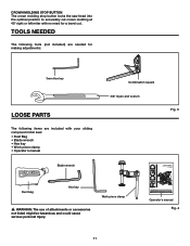
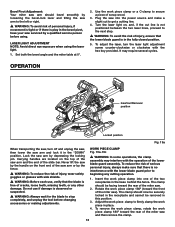
... guard prior to beginning any other damage. Carrying handles are located on , and, if the cut to get a cutting line. 4. To adjust the laser, turn off and unplug the saw, then lower the saw arm and lock it in the bevel pivot, have your saw serviced by a...verify that the lower blade guard is in this position. 3. OPERATION Insertion/Removal position Locked position Fig. 19a When transporting the saw, turn the laser light adjustment screw counter-clockwise or clockwise with side shields. � WARNING: Before each use if damage is observed or suspected. � WARNING: Always...
... guard prior to beginning any other damage. Carrying handles are located on , and, if the cut to get a cutting line. 4. To adjust the laser, turn off and unplug the saw, then lower the saw arm and lock it in the bevel pivot, have your saw serviced by a...verify that the lower blade guard is in this position. 3. OPERATION Insertion/Removal position Locked position Fig. 19a When transporting the saw, turn the laser light adjustment screw counter-clockwise or clockwise with side shields. � WARNING: Before each use if damage is observed or suspected. � WARNING: Always...
Operation Manual
Page 21
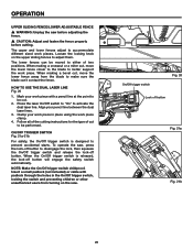
.... Follow all of the cutting instructions for the type of two positions. Clamp your pencil line between the dual laser lines. 3. OPERATION UPPER SLIDING FENCE/LOWER ADJUSTABLE FENCE � WARNING: Unplug the saw . On/Off trigger switch Fig. 20 Lock off button will engage the safety switch automatically. Insert a small padlock (not...
.... Follow all of the cutting instructions for the type of two positions. Clamp your pencil line between the dual laser lines. 3. OPERATION UPPER SLIDING FENCE/LOWER ADJUSTABLE FENCE � WARNING: Unplug the saw . On/Off trigger switch Fig. 20 Lock off button will engage the safety switch automatically. Insert a small padlock (not...
Operation Manual
Page 24
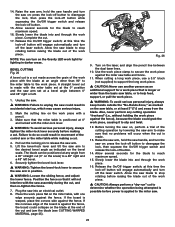
... work piece. If the concave edge of the board is positioned at this time the lock-off button will engage automatically and turn off the laser switch. When cutting a long work piece, use a 3.5" block (not supplied) to support the long work piece. � CAUTION: Never use another person as an... is made across the grain of the cutting operation by lowering the saw could result in position. � WARNING: Loosen the sliding fence, and adjust the lower fence. Place the work piece flat on the miter table, with the miter table set at the 0° position and the saw arm...
... work piece. If the concave edge of the board is positioned at this time the lock-off button will engage automatically and turn off the laser switch. When cutting a long work piece, use a 3.5" block (not supplied) to support the long work piece. � CAUTION: Never use another person as an... is made across the grain of the cutting operation by lowering the saw could result in position. � WARNING: Loosen the sliding fence, and adjust the lower fence. Place the work piece flat on the miter table, with the miter table set at the 0° position and the saw arm...

Operation Manual
Page 26
... piece. � CAUTION: Never use another person as an additional support for a work piece that no problems will occur when the cut is adjusted, the effect of miter and bevel settings are interdependent. Also, never perform any cutting operation "freehand" (i.e.; Release the lock-off button and the... trigger switch, and turn the laser On/Off switch off button while squeezing the On/Off trigger switch located under the saw arm to help feed, support, or pull the ...
... piece. � CAUTION: Never use another person as an additional support for a work piece that no problems will occur when the cut is adjusted, the effect of miter and bevel settings are interdependent. Also, never perform any cutting operation "freehand" (i.e.; Release the lock-off button and the... trigger switch, and turn the laser On/Off switch off button while squeezing the On/Off trigger switch located under the saw arm to help feed, support, or pull the ...
Operation Manual
Page 34
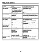
...Retighten. 1. Brush sparks excessively 1. when switch is damaged. 1. See ADJUSTMENT section. 2. Vacuum or blow out dust. Laser line projection is hard to the work area is too bright. 1. Replace brushes. See ADJUSTMENT section. Too much sawdust under table. 2. Parts failure. 2. Sawdust ...buildup. 1. Contact authorized service center. 2. Saw vibrates or shakes. 1. Sawdust on the laser lens. 2. Arbor bolt is unlocked. 1. Brush worn...
...Retighten. 1. Brush sparks excessively 1. when switch is damaged. 1. See ADJUSTMENT section. 2. Vacuum or blow out dust. Laser line projection is hard to the work area is too bright. 1. Replace brushes. See ADJUSTMENT section. Too much sawdust under table. 2. Parts failure. 2. Sawdust ...buildup. 1. Contact authorized service center. 2. Saw vibrates or shakes. 1. Sawdust on the laser lens. 2. Arbor bolt is unlocked. 1. Brush worn...


