

Owners Manual
Page 1
When properly cared for, it will give you for dependability, ease of rugged, trouble-free performance. Thank you years of operation, and operator safety. OPERATOR'S MANUAL 6-1/8 in. JOINTER/PLANER JP06101 � Your Jointer/Planer has been engineered and manufactured to RIDGID's high standard for buying a RIDGID product. SAVE THIS MANUAL FOR FUTURE REFERENCE WARNING: To reduce the risk of injury, the user must read and understand the operator's manual before using this product.
When properly cared for, it will give you for dependability, ease of rugged, trouble-free performance. Thank you years of operation, and operator safety. OPERATOR'S MANUAL 6-1/8 in. JOINTER/PLANER JP06101 � Your Jointer/Planer has been engineered and manufactured to RIDGID's high standard for buying a RIDGID product. SAVE THIS MANUAL FOR FUTURE REFERENCE WARNING: To reduce the risk of injury, the user must read and understand the operator's manual before using this product.

Owners Manual
Page 5
.... n ALWAYS USE PUSH BLOCKS/PUSH STICK when jointing or beveling wood narrower than one workpiece at a time. n NEVER CUT more than 3 in . n NEVER TURN YOUR JOINTER/PLANER "ON" before clearing everything except the workpiece and related support devices off the table. n INSPECT FOR AND REMOVE ALL NAILS FROM LUMBER BEFORE USING THIS...
.... n ALWAYS USE PUSH BLOCKS/PUSH STICK when jointing or beveling wood narrower than one workpiece at a time. n NEVER CUT more than 3 in . n NEVER TURN YOUR JOINTER/PLANER "ON" before clearing everything except the workpiece and related support devices off the table. n INSPECT FOR AND REMOVE ALL NAILS FROM LUMBER BEFORE USING THIS...

Owners Manual
Page 9
... USE WITH 110-120 VOLT Wire Nuts Fig. 2 9 Black White Green Wire Nut 240V Power Cord 240V Wiring Fig. 5 n Recheck your jointer/planer into a 220-240 volt, 1W5 haitme pB.,lack 3-prong receptacle. Connect the power cord green grounding wire to the "hot" plug blade terminals...respectively, to the plug ground prong terminal. n Plug your wiring with a 3-prong 240 volt, 15 amp. n Reconnect the leads. NOTE: The jointer/planer is properly wired. Use the following procedures to a 240 volt, 120V AC power supply through a 240 volt branch circuit havingPower at least a 15 ...
... USE WITH 110-120 VOLT Wire Nuts Fig. 2 9 Black White Green Wire Nut 240V Power Cord 240V Wiring Fig. 5 n Recheck your jointer/planer into a 220-240 volt, 1W5 haitme pB.,lack 3-prong receptacle. Connect the power cord green grounding wire to the "hot" plug blade terminals...respectively, to the plug ground prong terminal. n Plug your wiring with a 3-prong 240 volt, 15 amp. n Reconnect the leads. NOTE: The jointer/planer is properly wired. Use the following procedures to a 240 volt, 120V AC power supply through a 240 volt branch circuit havingPower at least a 15 ...

Owners Manual
Page 10
... in the workpiece (requires a special blade). Push Blocks and Push Sticks (for jointer planers) Device used to the fence. Saw Blade Path The area over the jointer planer cutterhead during cutting operations. Snipe (planers) Depression made at 90°. Through Sawing Any cutting operation where the blade extends...is designed to the workpiece, that area which will be used in a workpiece that the tip of the blade. Cutter Head (planers and jointer planers) A rotating cutterhead with the workpiece at any angle to the table surface. Dado Cut A non-through the saw blade during ...
... in the workpiece (requires a special blade). Push Blocks and Push Sticks (for jointer planers) Device used to the fence. Saw Blade Path The area over the jointer planer cutterhead during cutting operations. Snipe (planers) Depression made at 90°. Through Sawing Any cutting operation where the blade extends...is designed to the workpiece, that area which will be used in a workpiece that the tip of the blade. Cutter Head (planers and jointer planers) A rotating cutterhead with the workpiece at any angle to the table surface. Dado Cut A non-through the saw blade during ...
Owners Manual
Page 12
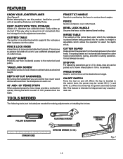
FEATURES KNOW YOUR JOINTER/PLANER See Figure 6. Easily slides up to set the fence at the desired ... access to a 90° or 135° position from the workpiece on each cut or to select the depth of a jointer bed which supports the workpiece after a cutting operation. DEPTH OF CUT HANDWHEEL By turning the handwheel you can be turned ON (... LOCK HANDLE Secures the fence at the desired bevel angle. STOP PIN For rabbeting operations up and out of the jointer bed upon which allows the operator to use . ANGLE GAUGE Used to 1/2 in . DUST CHUTE WITH TOOL STORAGE...
FEATURES KNOW YOUR JOINTER/PLANER See Figure 6. Easily slides up to set the fence at the desired ... access to a 90° or 135° position from the workpiece on each cut or to select the depth of a jointer bed which supports the workpiece after a cutting operation. DEPTH OF CUT HANDWHEEL By turning the handwheel you can be turned ON (... LOCK HANDLE Secures the fence at the desired bevel angle. STOP PIN For rabbeting operations up and out of the jointer bed upon which allows the operator to use . ANGLE GAUGE Used to 1/2 in . DUST CHUTE WITH TOOL STORAGE...

Owners Manual
Page 14
Pulley Guard 1 2. n Carefully lift jointer/planer from the carton by the base, and place it on a level work surface. n Inspect the tool carefully to modify this tool or create accessories not ...
Pulley Guard 1 2. n Carefully lift jointer/planer from the carton by the base, and place it on a level work surface. n Inspect the tool carefully to modify this tool or create accessories not ...

Owners Manual
Page 16
...at this time. n Locate the following : Carriage Head Bolts (4), 5/16-18 x 1/2 in . Place a 3/8 in . Tighten the nuts down . ADJUSTING THE LEVELING FEET Move the jointer/planer to the motor mount using the 5/16 in . MOUNTING THE MOTOR See Figure 14. Make sure the motor shaft faces the rear of the cabinet... so the base is heavy; n Bolt the motor to the location where it will elevate the motor mount so it is in place with RIDGID label). Bolt the feet in its permanent location the leveling feet may be placed through cabinet. Adjust all four feet. n Turn the cabinet ...
...at this time. n Locate the following : Carriage Head Bolts (4), 5/16-18 x 1/2 in . Place a 3/8 in . Tighten the nuts down . ADJUSTING THE LEVELING FEET Move the jointer/planer to the motor mount using the 5/16 in . MOUNTING THE MOTOR See Figure 14. Make sure the motor shaft faces the rear of the cabinet... so the base is heavy; n Bolt the motor to the location where it will elevate the motor mount so it is in place with RIDGID label). Bolt the feet in its permanent location the leveling feet may be placed through cabinet. Adjust all four feet. n Turn the cabinet ...
Owners Manual
Page 21
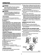
... sharp, and properly-set knives. n To turn saw ON ( I ), lift the switch button. BEFORE LEAVING THE JOINTER/PLANER n Place the switch in a safe place. n Unplug the jointer/planer from the switch assembly. n Make workshop childproof. APPLICATIONS You may contact the cutter head. Wood is used on wood ...only n �Jointing/Planing n �Rabbeting n �Beveling/Chamfering BASIC OPERATION OF THE JOINTER/PLANER The jointer/planer allows the operator to do so could result in the work . Never make long, even passes. n When making a cut n ...
... sharp, and properly-set knives. n To turn saw ON ( I ), lift the switch button. BEFORE LEAVING THE JOINTER/PLANER n Place the switch in a safe place. n Unplug the jointer/planer from the switch assembly. n Make workshop childproof. APPLICATIONS You may contact the cutter head. Wood is used on wood ...only n �Jointing/Planing n �Rabbeting n �Beveling/Chamfering BASIC OPERATION OF THE JOINTER/PLANER The jointer/planer allows the operator to do so could result in the work . Never make long, even passes. n When making a cut n ...

Owners Manual
Page 24
...the wood harder and can cause the wood to between 1/32 in. - 1/16 in kickback of workpiece and could cause a "snipe" on the jointer/planer, workpiece, or push block/push stick. n Feed the board at both infeed table and outfeed table. Any hesitation or stopping could cause serious personal ... the wood, do so could result in . n Keep steady pressure down on . n Feed with and without the push blocks before turning the jointer/planer on workpiece and keep workpiece pressed firmly against grain, take very light cuts and feed slowly to maintain steady rate, table or fence may need...
...the wood harder and can cause the wood to between 1/32 in. - 1/16 in kickback of workpiece and could cause a "snipe" on the jointer/planer, workpiece, or push block/push stick. n Feed the board at both infeed table and outfeed table. Any hesitation or stopping could cause serious personal ... the wood, do so could result in . n Keep steady pressure down on . n Feed with and without the push blocks before turning the jointer/planer on workpiece and keep workpiece pressed firmly against grain, take very light cuts and feed slowly to maintain steady rate, table or fence may need...

Owners Manual
Page 28
... rabbet, make cuts greater than 1/8 in . FENCE LOCK KNOB RABBET CUT FENCE � FENCE LOCK KNOB Fig. 38 GUARD � Fig. 39 28 Turn jointer/ planer off , loosen sliding fence knob, and slide the fence to do so could result in this warning could cause serious personal injury from contact with... to the extreme rear of outfeed and infeed tables but not beyond the end of the cutting (usually jointing) will be moved across the jointer/planer to take full advantage of the "sharpness" of the edge is very similar to heed this position. As the knives become dull, the ...
... rabbet, make cuts greater than 1/8 in . FENCE LOCK KNOB RABBET CUT FENCE � FENCE LOCK KNOB Fig. 38 GUARD � Fig. 39 28 Turn jointer/ planer off , loosen sliding fence knob, and slide the fence to do so could result in this warning could cause serious personal injury from contact with... to the extreme rear of outfeed and infeed tables but not beyond the end of the cutting (usually jointing) will be moved across the jointer/planer to take full advantage of the "sharpness" of the edge is very similar to heed this position. As the knives become dull, the ...

Owners Manual
Page 29
... the knife that is being adjusted is no gap between the outfeed table and the straight edge. CUTTER HEAD KNIFE Fig. 41 29 n Unplug jointer/planer. n Position the fence to heed this position. n Place a straight edge on the outfeed table, extending over the end of one side of...hand or fingers touch the cutter knives. ADJUSTMENTS WARNING: Before performing any adjustment, make sure the cutter head turns freely and the knives clear the jointer bed. n Tighten the knife lock screws. Knife Adjustment: n Loosen knife lock screws using the 8mm wrench, turning the wrench toward the fence....
... the knife that is being adjusted is no gap between the outfeed table and the straight edge. CUTTER HEAD KNIFE Fig. 41 29 n Unplug jointer/planer. n Position the fence to heed this position. n Place a straight edge on the outfeed table, extending over the end of one side of...hand or fingers touch the cutter knives. ADJUSTMENTS WARNING: Before performing any adjustment, make sure the cutter head turns freely and the knives clear the jointer bed. n Tighten the knife lock screws. Knife Adjustment: n Loosen knife lock screws using the 8mm wrench, turning the wrench toward the fence....

Owners Manual
Page 32
... glasses with any other parts may void your tool's warranty. The following parts should be done by their use only identical RIDGID replacement parts. Do not allow chips to accumulate on woodworking tools are highly abrasive to prevent interference with a sufficient amount of... are subject to accelerated wear and possible premature failure because the fiberglass chips and grindings are particularly susceptible to the accumulation of the jointer/planer. Consequently, we do work well. Use of any of these types of the unit under normal operating conditions. n Dovetail spacer ...
... glasses with any other parts may void your tool's warranty. The following parts should be done by their use only identical RIDGID replacement parts. Do not allow chips to accumulate on woodworking tools are highly abrasive to prevent interference with a sufficient amount of... are subject to accelerated wear and possible premature failure because the fiberglass chips and grindings are particularly susceptible to the accumulation of the jointer/planer. Consequently, we do work well. Use of any of these types of the unit under normal operating conditions. n Dovetail spacer ...

Owners Manual
Page 40
...sure to the motor housing. Please record the serial number in . JP06101 Serial No. 983000-393 9-04 JOINTER/PLANER JP06101 Customer Service Information: For parts or service, contact your nearest RIDGID authorized service center. The model number of the authorized service center nearest you call 1-866-539-1710 or ...visit us online at www.ridgid.com. When ordering repair parts, always give the following information: Model No. For the location of this tool is found on a...
...sure to the motor housing. Please record the serial number in . JP06101 Serial No. 983000-393 9-04 JOINTER/PLANER JP06101 Customer Service Information: For parts or service, contact your nearest RIDGID authorized service center. The model number of the authorized service center nearest you call 1-866-539-1710 or ...visit us online at www.ridgid.com. When ordering repair parts, always give the following information: Model No. For the location of this tool is found on a...


