

Owners Manual
Page 3
... cord will draw. A wire gauge size (A.W.G.) of power and overheating. Be sure switch is in loss of at all instructions. Never carry tool by removing starter keys. Sharp blades minimize stalling and kickback. GENERAL SAFETY RULES WARNING: Read and understand all times. READ ALL INSTRUCTIONS n KNOW YOUR POWER TOOL. Read the operator's manual carefully. Learn the applications and limitations as well as specific potential hazards related to operate the tool. n REMOVE ADJUSTING KEYS...
... cord will draw. A wire gauge size (A.W.G.) of power and overheating. Be sure switch is in loss of at all instructions. Never carry tool by removing starter keys. Sharp blades minimize stalling and kickback. GENERAL SAFETY RULES WARNING: Read and understand all times. READ ALL INSTRUCTIONS n KNOW YOUR POWER TOOL. Read the operator's manual carefully. Learn the applications and limitations as well as specific potential hazards related to operate the tool. n REMOVE ADJUSTING KEYS...

Owners Manual
Page 4
... replacement parts. Make sure the spindle or sanding belt assembly is tight and not making contact with the accessory. n DO NOT USE TOOL IF SWITCH DOES NOT TURN IT ON AND OFF. n INSPECT FOR AND REMOVE ALL NAILS FROM LUMBER BEFORE USING THIS TOOL. n WHEN SERVICING use a clean cloth when cleaning. n NEVER START A TOOL WHEN ANY ROTATING COMPONENT IS IN CONTACT WITH THE WORKPIECE. n KEEP TOOL DRY, CLEAN, AND FREE FROM OIL...
... replacement parts. Make sure the spindle or sanding belt assembly is tight and not making contact with the accessory. n DO NOT USE TOOL IF SWITCH DOES NOT TURN IT ON AND OFF. n INSPECT FOR AND REMOVE ALL NAILS FROM LUMBER BEFORE USING THIS TOOL. n WHEN SERVICING use a clean cloth when cleaning. n NEVER START A TOOL WHEN ANY ROTATING COMPONENT IS IN CONTACT WITH THE WORKPIECE. n KEEP TOOL DRY, CLEAN, AND FREE FROM OIL...

Owners Manual
Page 5
..., plane or bevel workpieces shorter than 3/4 in . n INSPECT FOR AND REMOVE ALL NAILS FROM LUMBER BEFORE USING THIS TOOL. n ALWAYS USE PUSH BLOCKS/PUSH STICK when planing. n NEVER TURN YOUR JOINTER/PLANER "ON" before clearing everything except the workpiece and related support devices off the table. Refer to them frequently and use either the rip fence or miter fence to position and guide the work . n PROTECT...
..., plane or bevel workpieces shorter than 3/4 in . n INSPECT FOR AND REMOVE ALL NAILS FROM LUMBER BEFORE USING THIS TOOL. n ALWAYS USE PUSH BLOCKS/PUSH STICK when planing. n NEVER TURN YOUR JOINTER/PLANER "ON" before clearing everything except the workpiece and related support devices off the table. Refer to them frequently and use either the rip fence or miter fence to position and guide the work . n PROTECT...
Owners Manual
Page 7
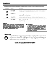
... when needed. Before beginning power tool operation, always wear safety goggles or safety glasses with this product. SAVE THESE INSTRUCTIONS 7 Indicates a potentially hazardous situation, which, if not avoided, may result in minor or moderate injury. (Without Safety Alert Symbol) Indicates a situation that may use this product. WARNING: To avoid serious personal injury, do not attempt to use this operator's manual and review frequently...
... when needed. Before beginning power tool operation, always wear safety goggles or safety glasses with this product. SAVE THESE INSTRUCTIONS 7 Indicates a potentially hazardous situation, which, if not avoided, may result in minor or moderate injury. (Without Safety Alert Symbol) Indicates a situation that may use this product. WARNING: To avoid serious personal injury, do not attempt to use this operator's manual and review frequently...

Owners Manual
Page 8
... conductor to support two or three tools. Check with an electric cord having an outer surface that is properly installed and grounded in figure 1. Do not operate this tool is properly grounded. SPEED AND WIRING The no-load speed of this tool on the cord's jacket. Improper connection of the equipment-grounding conductor can result in an extension cord. If repair or replacement of the working area...
... conductor to support two or three tools. Check with an electric cord having an outer surface that is properly installed and grounded in figure 1. Do not operate this tool is properly grounded. SPEED AND WIRING The no-load speed of this tool on the cord's jacket. Improper connection of the equipment-grounding conductor can result in an extension cord. If repair or replacement of the working area...

Owners Manual
Page 10
... the table or fence during a ripping operation. Cutter Head (planers and jointer planers) A rotating cutterhead with the blade. Arbor The shaft on which a blade or cutting tool is mounted. Chamfer A cut without the workpiece being guided by guiding it applies to the workpiece, that serves as a guide for table saws) Devices used to feed the workpiece over , under, behind, or in contact with adjustable blades or knives. Featherboard A device used in...
... the table or fence during a ripping operation. Cutter Head (planers and jointer planers) A rotating cutterhead with the blade. Arbor The shaft on which a blade or cutting tool is mounted. Chamfer A cut without the workpiece being guided by guiding it applies to the workpiece, that serves as a guide for table saws) Devices used to feed the workpiece over , under, behind, or in contact with adjustable blades or knives. Featherboard A device used in...

Owners Manual
Page 11
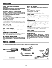
... OUTFEED TABLE Cutter Head 3 Knives Input 120 V, 60 Hz, AC only, 12.0 Amps Input 240 V, 60 Hz, AC only, 6.0 Amps Net Weight 208 lbs. FEATURES PRODUCT SPECIFICATIONS Motor 1 HP Induction Phase Single Rotation of Shaft Counterclockwise No Load Speed 3450/min. FENCE LOCK KNOB CUTTER GUARD FENCE TILT HANDLE FENCE DEPTH INDICATOR INFEED TABLE STOP PIN FENCE STOPS � ON OFF SWITCH DEPTH OF CUT HANDWHEEL PUSH BLOCKS ANGLE GAUGE FENCE LOCK KNOB BEVEL LOCK HANDLE PULLEY GUARD TABLE LOCK SCREW OUTFEED TABLE HANDWHEEL DUST CHUTE WITH TOOL STORAGE...
... OUTFEED TABLE Cutter Head 3 Knives Input 120 V, 60 Hz, AC only, 12.0 Amps Input 240 V, 60 Hz, AC only, 6.0 Amps Net Weight 208 lbs. FEATURES PRODUCT SPECIFICATIONS Motor 1 HP Induction Phase Single Rotation of Shaft Counterclockwise No Load Speed 3450/min. FENCE LOCK KNOB CUTTER GUARD FENCE TILT HANDLE FENCE DEPTH INDICATOR INFEED TABLE STOP PIN FENCE STOPS � ON OFF SWITCH DEPTH OF CUT HANDWHEEL PUSH BLOCKS ANGLE GAUGE FENCE LOCK KNOB BEVEL LOCK HANDLE PULLEY GUARD TABLE LOCK SCREW OUTFEED TABLE HANDWHEEL DUST CHUTE WITH TOOL STORAGE...
Owners Manual
Page 12
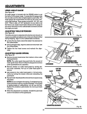
... be turned ON. ANGLE GAUGE Used to lock infeed or outfeed table at a desired height. Before attempting to help prevent any unauthorized use this product, familiarize yourself with all operating Features and Safety Rules. Also tool storage for making adjustments or installing the knives: PHILLIPS SCREWDRIVER STRAIGHT EDGE ADJUSTABLE WRENCH OPEN END WRENCH (1/2 IN.) COMBINATION SQUARE Fig. 7 12 This feature is spring loaded so it passes over cutter head. TOOLS NEEDED FENCE TILT HANDLE Assists...
... be turned ON. ANGLE GAUGE Used to lock infeed or outfeed table at a desired height. Before attempting to help prevent any unauthorized use this product, familiarize yourself with all operating Features and Safety Rules. Also tool storage for making adjustments or installing the knives: PHILLIPS SCREWDRIVER STRAIGHT EDGE ADJUSTABLE WRENCH OPEN END WRENCH (1/2 IN.) COMBINATION SQUARE Fig. 7 12 This feature is spring loaded so it passes over cutter head. TOOLS NEEDED FENCE TILT HANDLE Assists...
Owners Manual
Page 18
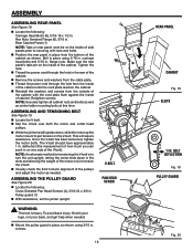
... using 3/16 in. n Remove the screws and washers from the inside of side panels prior to back alignment of the V-belt). Retighten screws. n Locate the V-belt. Once the V-belt has been tensioned, tighten the motor bolts. n Visually check the front to securing with nuts and bolts. Hex Nuts Serrated Flange (6), 5/16 in . n Thread the power cord through the hole from the cable plate. n Slip the V-belt...
... using 3/16 in. n Remove the screws and washers from the inside of side panels prior to back alignment of the V-belt). Retighten screws. n Locate the V-belt. Once the V-belt has been tensioned, tighten the motor bolts. n Visually check the front to securing with nuts and bolts. Hex Nuts Serrated Flange (6), 5/16 in . n Thread the power cord through the hole from the cable plate. n Slip the V-belt...

Owners Manual
Page 20
... the bed for proper clearance and function. Do not position fence beyond rear edge of cutter guard travel. Tap the post slightly to the rear of the guard, the post is inserted too deeply. n Locate the following: Cutter Guard Assembly (1) n Remove the pan head screw from up under the table with a punch or nail set. Slide the post through the hole in the infeed...
... the bed for proper clearance and function. Do not position fence beyond rear edge of cutter guard travel. Tap the post slightly to the rear of the guard, the post is inserted too deeply. n Locate the following: Cutter Guard Assembly (1) n Remove the pan head screw from up under the table with a punch or nail set. Slide the post through the hole in the infeed...
Owners Manual
Page 21
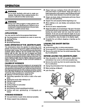
... most operations. n Do not cut without stopping or backing up , or improperly set knives. To be ready to edge. n Make workshop childproof. AVOIDING KICKBACK n Use push blocks or push sticks whenever possible. n To turn saw ON ( I ), lift the switch button. n Remove the switch key from the power source. Store key in a safe place. APPLICATIONS You may contact the cutter head. piece n Twisting the wood while making a cut n Cutting warped...
... most operations. n Do not cut without stopping or backing up , or improperly set knives. To be ready to edge. n Make workshop childproof. AVOIDING KICKBACK n Use push blocks or push sticks whenever possible. n To turn saw ON ( I ), lift the switch button. n Remove the switch key from the power source. Store key in a safe place. APPLICATIONS You may contact the cutter head. piece n Twisting the wood while making a cut n Cutting warped...

Owners Manual
Page 26
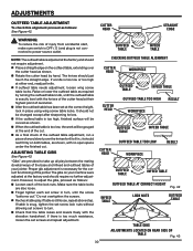
...° stop . n Loosen the jam nut on the outfeed table and check fence while locked in . n Using the angle gauge, square the fence to power source outlet. This tool provides bevel stops at 90°, 45°, or 135°, perform the following procedure: SETTING THE FENCE FOR A 90° BEVEL STOP See Figure 36. If the fence is not connected to the outfeed table and tighten the bevel lock handle. n Turn the stop screw so it...
...° stop . n Loosen the jam nut on the outfeed table and check fence while locked in . n Using the angle gauge, square the fence to power source outlet. This tool provides bevel stops at 90°, 45°, or 135°, perform the following procedure: SETTING THE FENCE FOR A 90° BEVEL STOP See Figure 36. If the fence is not connected to the outfeed table and tighten the bevel lock handle. n Turn the stop screw so it...

Owners Manual
Page 27
... check the angle using the included angle gauge. n Loosen the bevel lock knob. n Make sure fence is tight against the stop screw. n Turn the stop screw so it contacts the 135° stop . n Move the fence to any angle and then return it to the outfeed table and tighten the bevel lock handle. FENCE LOCK KNOB FENCE � 135° STOP SCREW BEVEL LOCK HANDLE ANGLE GAUGE Fig. 37 27 Tighten the jam nut. n Loosen bevel lock handle. Check for accuracy with the angle gauge. n Using the angle gauge, set the fence at 135...
... check the angle using the included angle gauge. n Loosen the bevel lock knob. n Make sure fence is tight against the stop screw. n Turn the stop screw so it contacts the 135° stop . n Move the fence to any angle and then return it to the outfeed table and tighten the bevel lock handle. FENCE LOCK KNOB FENCE � 135° STOP SCREW BEVEL LOCK HANDLE ANGLE GAUGE Fig. 37 27 Tighten the jam nut. n Loosen bevel lock handle. Check for accuracy with the angle gauge. n Using the angle gauge, set the fence at 135...

Owners Manual
Page 28
... position. To move the fence, turn jointer/planer off and wait for all parts to heed this position. When knives are sharper. FENCE LOCK KNOB RABBET CUT FENCE � FENCE LOCK KNOB Fig. 38 GUARD � Fig. 39 28 Rabbeting is supported by the outfeed table during a rabbet cut , the fence can injure. WARNING: Never remove the cutter head guard when performing any operation. Do not make cuts in 1/8 in . n Hold...
... position. To move the fence, turn jointer/planer off and wait for all parts to heed this position. When knives are sharper. FENCE LOCK KNOB RABBET CUT FENCE � FENCE LOCK KNOB Fig. 38 GUARD � Fig. 39 28 Rabbeting is supported by the outfeed table during a rabbet cut , the fence can injure. WARNING: Never remove the cutter head guard when performing any operation. Do not make cuts in 1/8 in . n Hold...

Owners Manual
Page 29
... tool is unplugged from the power supply and the switch is no gap between the outfeed table and the straight edge. n Place a straight edge on the outfeed table, extending over the cutter head as shown. Check all the parts and clean thoroughly with the straight edge to figure 40 when reinstalling knives. Knife Adjustment: n Loosen knife lock screws using the 8mm wrench, turning the wrench toward the fence. Remove...
... tool is unplugged from the power supply and the switch is no gap between the outfeed table and the straight edge. n Place a straight edge on the outfeed table, extending over the cutter head as shown. Check all the parts and clean thoroughly with the straight edge to figure 40 when reinstalling knives. Knife Adjustment: n Loosen knife lock screws using the 8mm wrench, turning the wrench toward the fence. Remove...
Owners Manual
Page 30
... power source outlet. The knives should rest firmly on the outfeed table, extending over the knives for the correct functioning of injury from accidental start, make sure switch is OFF ( O ) and plug is still loose, repeat above step. n If outfeed table needs adjustment, loosen wing screw table locks. Proper gib adjustment is snug, tighten the set screw lock nuts without allowing set at the end of the cut...
... power source outlet. The knives should rest firmly on the outfeed table, extending over the knives for the correct functioning of injury from accidental start, make sure switch is OFF ( O ) and plug is still loose, repeat above step. n If outfeed table needs adjustment, loosen wing screw table locks. Proper gib adjustment is snug, tighten the set screw lock nuts without allowing set at the end of the cut...
Owners Manual
Page 31
... operation. n Using a straight edge, align the extension to be flush with the RIDGID jointer to set the fence to the cutter head guard in service. n Repeat Cutter Head Guard Functional Check as follows. Overtightening may cause premature spring or guard breakage. ADJUSTING GUARD SPRING See Figure 46. n Remove the pan head screw from bottom of the more common angle settings. EXTENSION SLOT PAN HEAD SCREW CUTTER GUARD STOP POST � CUTTER GUARD ANGLE GAUGE Fig. 44 OUTFEED TABLE SOCKET HEAD SCREW...
... operation. n Using a straight edge, align the extension to be flush with the RIDGID jointer to set the fence to the cutter head guard in service. n Repeat Cutter Head Guard Functional Check as follows. Overtightening may cause premature spring or guard breakage. ADJUSTING GUARD SPRING See Figure 46. n Remove the pan head screw from bottom of the more common angle settings. EXTENSION SLOT PAN HEAD SCREW CUTTER GUARD STOP POST � CUTTER GUARD ANGLE GAUGE Fig. 44 OUTFEED TABLE SOCKET HEAD SCREW...

Owners Manual
Page 32
.... Clean them with side shields during power tool operation or when blowing dust. Electric tools used on woodworking tools are particularly susceptible to the accumulation of these types of high grade lubricant for your model. n If the motor won't start , refer to accumulate on the underside of the motor should be done by their use only identical RIDGID replacement parts. For heavy loads, however, the voltage at any...
.... Clean them with side shields during power tool operation or when blowing dust. Electric tools used on woodworking tools are particularly susceptible to the accumulation of these types of high grade lubricant for your model. n If the motor won't start , refer to accumulate on the underside of the motor should be done by their use only identical RIDGID replacement parts. For heavy loads, however, the voltage at any...
Owners Manual
Page 35
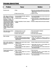
... 3. Pulley set screw. Tighten set screw is capable, and a reduction of 20% in voltage causes a reduction of power company facilities 1. TROUBLESHOOTING Problem Cause Solution Excessive noise 1. Request a voltage check from the power company. 2. Have motor repaired or replaced. 2. Drive belt tension too high 3. Fuses or circuit breakers do not have sufficient capacity 3. Clean out sawdust to provide normal air circulation through motor due to full speed 1. Motor overheats 1.
... 3. Pulley set screw. Tighten set screw is capable, and a reduction of 20% in voltage causes a reduction of power company facilities 1. TROUBLESHOOTING Problem Cause Solution Excessive noise 1. Request a voltage check from the power company. 2. Have motor repaired or replaced. 2. Drive belt tension too high 3. Fuses or circuit breakers do not have sufficient capacity 3. Clean out sawdust to provide normal air circulation through motor due to full speed 1. Motor overheats 1.

Owners Manual
Page 39
... RIDGID® Hand Held and Stationary Power Tools covers all original equipment packaged with the original product. To receive a replacement tool you by calling (toll free) 1-866-539-1710 or by One World Technologies, Inc. When requesting warranty service, you may obtain the location of MERCHANTABILITY or FITNESS FOR A PARTICULAR PURPOSE, are dissatisfied with the tool such as brushes, chucks, motors, switches, cords, gears and even cordless batteries...
... RIDGID® Hand Held and Stationary Power Tools covers all original equipment packaged with the original product. To receive a replacement tool you by calling (toll free) 1-866-539-1710 or by One World Technologies, Inc. When requesting warranty service, you may obtain the location of MERCHANTABILITY or FITNESS FOR A PARTICULAR PURPOSE, are dissatisfied with the tool such as brushes, chucks, motors, switches, cords, gears and even cordless batteries...


