Operating Instructions
Page 2
... to USER SAFETY and PREVENTING EQUIPMENT PROBLEMS. Notes: Some illustrations might occur. 11. When the machine is not an ANSI-compliant shielded SCSI-2 cable could cause and electric shock or fire. 10. Power requirements: 220-240 V, 50/60 Hz, 5A or more than necessary. These actions...wall socket. 3. Do not connect other equipment to the same socket. 5. Do not connect other equipment to the same extension cord. 7. Using a cable that exceed the limits of the EMC Directive . Power Supply 1. When you move the machine, unplug the power cord from your local dealer. Wait...
... to USER SAFETY and PREVENTING EQUIPMENT PROBLEMS. Notes: Some illustrations might occur. 11. When the machine is not an ANSI-compliant shielded SCSI-2 cable could cause and electric shock or fire. 10. Power requirements: 220-240 V, 50/60 Hz, 5A or more than necessary. These actions...wall socket. 3. Do not connect other equipment to the same socket. 5. Do not connect other equipment to the same extension cord. 7. Using a cable that exceed the limits of the EMC Directive . Power Supply 1. When you move the machine, unplug the power cord from your local dealer. Wait...
Operating Instructions
Page 3
In accordance with the requirements of the EMC Directive 89/336/EEC and the Low Voltage Directive 73/23/EEC." Declaration of Conformity "The Product complies with IEC417, this machine uses the following symbols for connections to host computer (and/or peripheral) in order to meet EMC Directive 89/336/EEC emission limits. Caution Properly shielded and grounded cables and connectors must be used for the main switch: • a means Push ON Push OFF RICOH IMAGE SCANNER IS450S/IS450D/IS450SE/IS450DE Copyright © 1998
In accordance with the requirements of the EMC Directive 89/336/EEC and the Low Voltage Directive 73/23/EEC." Declaration of Conformity "The Product complies with IEC417, this machine uses the following symbols for connections to host computer (and/or peripheral) in order to meet EMC Directive 89/336/EEC emission limits. Caution Properly shielded and grounded cables and connectors must be used for the main switch: • a means Push ON Push OFF RICOH IMAGE SCANNER IS450S/IS450D/IS450SE/IS450DE Copyright © 1998

Operating Instructions
Page 4
...radio /TV technician for the main switch: • a means Push ON Push OFF RICOH IMAGE SCANNER IS450S/IS450D/IS450SE/IS450DE Copyright © 1998 Caution Properly shielded and grounded cables and connectors must accept any interference received, including interference that interference will not occur in... B est conforme à la norme NMB-003 du Canada.. Declaration of Conformity Product Name: Scanner Model Number: RICOH IMAGE SCANNER IS450S/IS450D/IS450SE/IS450DE Responsible party: Ricoh Corporation Address: 5 Dedrick Place, West Caldwell, NJ 07006 Telephone number: 973-882-2000 This ...
...radio /TV technician for the main switch: • a means Push ON Push OFF RICOH IMAGE SCANNER IS450S/IS450D/IS450SE/IS450DE Copyright © 1998 Caution Properly shielded and grounded cables and connectors must accept any interference received, including interference that interference will not occur in... B est conforme à la norme NMB-003 du Canada.. Declaration of Conformity Product Name: Scanner Model Number: RICOH IMAGE SCANNER IS450S/IS450D/IS450SE/IS450DE Responsible party: Ricoh Corporation Address: 5 Dedrick Place, West Caldwell, NJ 07006 Telephone number: 973-882-2000 This ...
Operating Instructions
Page 11
... 1 Printing on scanned documents (optional 1 Space-saving design 2 Supports both TWAIN and ISIS 2 Guide to the Scanner 3 Understanding the Indicators 5 2. Introduction Features 1 Ultra-fast scanning 1 Simultaneous scanning of both sides of Indications i Important Information iv How to Other Port 12 Connecting the Power Cable 13 Turning On/Off the Scanner Power 15 Turning On...
... 1 Printing on scanned documents (optional 1 Space-saving design 2 Supports both TWAIN and ISIS 2 Guide to the Scanner 3 Understanding the Indicators 5 2. Introduction Features 1 Ultra-fast scanning 1 Simultaneous scanning of both sides of Indications i Important Information iv How to Other Port 12 Connecting the Power Cable 13 Turning On/Off the Scanner Power 15 Turning On...
Operating Instructions
Page 18
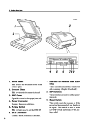
...Model only) 8. DIP Switches These switches are used to set the operating mode. 9. White Sheet This presses the document down on again. Reset Switch This switch resets the scanner as if the power had been turned off and then back on the contact glass. 2. Contact Glass This is ... SCSI ID. 6. This switch is used to clear paper jams, etc. 4. Introduction 1 2 TH2H020E 3 4 5 6 789 1. SCSI Connector Connect the SCSI interface cable here. 4 7. Power Connector Connect the power cable here. 5. ADF Cover Open this cover to make new DIP switch and rotary switch settings valid.
...Model only) 8. DIP Switches These switches are used to set the operating mode. 9. White Sheet This presses the document down on again. Reset Switch This switch resets the scanner as if the power had been turned off and then back on the contact glass. 2. Contact Glass This is ... SCSI ID. 6. This switch is used to clear paper jams, etc. 4. Introduction 1 2 TH2H020E 3 4 5 6 789 1. SCSI Connector Connect the SCSI interface cable here. 4 7. Power Connector Connect the power cable here. 5. ADF Cover Open this cover to make new DIP switch and rotary switch settings valid.
Operating Instructions
Page 24
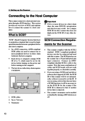
...are using a SCSI board and driver software that supports SCAM, the SCSI ID of this scanner will be connected and used to connect one or more devices in the daisy chain requires a terminator. 1: SCSI cables 2: Up to set the SCSI ID for highspeed data transfer between a peripheral device and... can also be necessary to set the ID. Connect an ANSIcompliant shielded SCSI-2 cable to a host personal computer through a SCSI interface. ments for the device before turning on the power and before turning on the scanner has a 50-pin half-pitch (pin type) connector. What is identical to...
...are using a SCSI board and driver software that supports SCAM, the SCSI ID of this scanner will be connected and used to connect one or more devices in the daisy chain requires a terminator. 1: SCSI cables 2: Up to set the SCSI ID for highspeed data transfer between a peripheral device and... can also be necessary to set the ID. Connect an ANSIcompliant shielded SCSI-2 cable to a host personal computer through a SCSI interface. ments for the device before turning on the power and before turning on the scanner has a 50-pin half-pitch (pin type) connector. What is identical to...

Operating Instructions
Page 25
...and the peripheral devices in - Refer to set the SCSI ID number. For details on the functions of the SCSI cables, in daisy chain fashion, with this scanner at the end of the daisy chain. (Use either of SCSI boards and peripheral devices that will be connected through... the power is on the scanner.) C Set DIP switch 3 to initialize the scanner. This enables the scanner's internal terminator. Connecting to the Host Computer Important Ì The total length of the DIP switches, refer to P.43, "DIP Switches." cluding the length of the cable inside the personal computer, should...
...and the peripheral devices in - Refer to set the SCSI ID number. For details on the functions of the SCSI cables, in daisy chain fashion, with this scanner at the end of the daisy chain. (Use either of SCSI boards and peripheral devices that will be connected through... the power is on the scanner.) C Set DIP switch 3 to initialize the scanner. This enables the scanner's internal terminator. Connecting to the Host Computer Important Ì The total length of the DIP switches, refer to P.43, "DIP Switches." cluding the length of the cable inside the personal computer, should...
Operating Instructions
Page 26
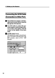
B Use SCSI cables to connect the personal computer and the peripheral devices in daisy chain fashion, with this scanner in the middle of the DIP switches, refer to P.43, "DIP Switches." 12 For details on . ripheral devices that will be connected through the SCSI interface. C Set DIP switch 3 to Other Port) A Turn off the host computer and all pe- 2. This disables the scanner's internal terminator. Setting up the Scanner Connecting the SCSI Cable (Connection to on the functions of the daisy chain.
B Use SCSI cables to connect the personal computer and the peripheral devices in daisy chain fashion, with this scanner in the middle of the DIP switches, refer to P.43, "DIP Switches." 12 For details on . ripheral devices that will be connected through the SCSI interface. C Set DIP switch 3 to Other Port) A Turn off the host computer and all pe- 2. This disables the scanner's internal terminator. Setting up the Scanner Connecting the SCSI Cable (Connection to on the functions of the daisy chain.

Operating Instructions
Page 27
... cord. Caution • When you pull out the plug from the socket, grip the plug to the scanner. Connecting the Power Cable Connecting the Power Cable This section explains how to connect the power cable to avoid damaging the cord and causing fire or electric shock. Failure to ground the... scanner. A Confirm that the power switch is no ground connection available, consult your hands wet. Warning • Be sure to ground the scanner could cause an electric shock...
... cord. Caution • When you pull out the plug from the socket, grip the plug to the scanner. Connecting the Power Cable Connecting the Power Cable This section explains how to connect the power cable to avoid damaging the cord and causing fire or electric shock. Failure to ground the... scanner. A Confirm that the power switch is no ground connection available, consult your hands wet. Warning • Be sure to ground the scanner could cause an electric shock...

Operating Instructions
Page 28
Note Ì Use the power cable that was provided with this scanner. Setting up the Scanner B Push the power cable plug all of the power cable into the power connector on the scanner. C Plug the other end of the way into the power outlet. 14 2.
Note Ì Use the power cable that was provided with this scanner. Setting up the Scanner B Push the power cable plug all of the power cable into the power connector on the scanner. C Plug the other end of the way into the power outlet. 14 2.
Operating Instructions
Page 41
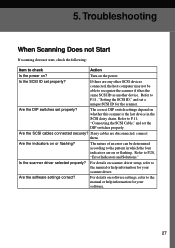
...If there are disconnected, connect them. If any cables are any other SCSI devices connected, the host computer may not be determined according to P.28, "Error Indicators and Solutions." Are the indicators on the power. For details on scanner driver setup, refer to the manual or help information...5. Are the DIP switches set properly? For details on software settings, refer to the manual or help information for the scanner. Turn on or flashing? Are the SCSI cables connected securey? The nature of an error can be able to P.11, "Setting the SCSI ID," and set the ...
...If there are disconnected, connect them. If any cables are any other SCSI devices connected, the host computer may not be determined according to P.28, "Error Indicators and Solutions." Are the indicators on the power. For details on scanner driver setup, refer to the manual or help information...5. Are the DIP switches set properly? For details on software settings, refer to the manual or help information for the scanner. Turn on or flashing? Are the SCSI cables connected securey? The nature of an error can be able to P.11, "Setting the SCSI ID," and set the ...

Operating Instructions
Page 44
... Too Light or the Original Gets Dirty Replacing the Ink Ribbon Caution: • When you pull out the plug from the power outlet. A Turn off scanner power, and unplug the power cable from the socket, grip the plug to avoid damaging the cord and causing fire or electric shock. 5.
... Too Light or the Original Gets Dirty Replacing the Ink Ribbon Caution: • When you pull out the plug from the power outlet. A Turn off scanner power, and unplug the power cable from the socket, grip the plug to avoid damaging the cord and causing fire or electric shock. 5.
Operating Instructions
Page 48
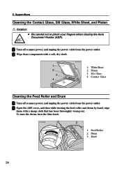
..., dry cloth. 1: White Sheet 2: Platen 3: Slit Glass 4: Contact Glass Cleaning the Feed Roller and Drum A Turn off scanner power, and unplug the power cable from the power outlet. 6. A Turn off scanner power, and unplug the power cable from the power outlet. To turn the drum, turn the blue knob. 1: Feed Roller 2: Drum 3: Knob 34... out. Appendices Cleaning the Contact Glass, Slit Glass, White Sheet, and Platen Caution: • Be careful not to pinch your fingers when closing the Auto Document Feeder (ADF).
..., dry cloth. 1: White Sheet 2: Platen 3: Slit Glass 4: Contact Glass Cleaning the Feed Roller and Drum A Turn off scanner power, and unplug the power cable from the power outlet. 6. A Turn off scanner power, and unplug the power cable from the power outlet. To turn the drum, turn the blue knob. 1: Feed Roller 2: Drum 3: Knob 34... out. Appendices Cleaning the Contact Glass, Slit Glass, White Sheet, and Platen Caution: • Be careful not to pinch your fingers when closing the Auto Document Feeder (ADF).
Operating Instructions
Page 50
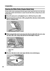
B Open the Auto Document Feeder (ADF), and pull off scanner power, and unplug the power cable from the reverse side of the original when a double-sided document is held in place by the arrow, wipe the white roller with a damp cloth that has been thoroughly wrung out. 1: White roller 2: Drum D Place the ...
B Open the Auto Document Feeder (ADF), and pull off scanner power, and unplug the power cable from the reverse side of the original when a double-sided document is held in place by the arrow, wipe the white roller with a damp cloth that has been thoroughly wrung out. 1: White roller 2: Drum D Place the ...

Operating Instructions
Page 53
... the sides, above the bottom, and with the Auto Document Feeder (ADF) closest to yourself, carry the scanner to dispose of the Scanner When you wish to its original shipping carton. Important Ì Disconnect all cables. Ì Because the scanner is a precision instrument, pack it carefully so that it as level as possible. Important Ì...
... the sides, above the bottom, and with the Auto Document Feeder (ADF) closest to yourself, carry the scanner to dispose of the Scanner When you wish to its original shipping carton. Important Ì Disconnect all cables. Ì Because the scanner is a precision instrument, pack it carefully so that it as level as possible. Important Ì...

Operating Instructions
Page 57
... these set the SCSI ID with the SCAM function enabled are connected on ON: Internal SCSI terminator off ). 43 Do not change . In this scanner is used, misoperation may occur during synchronous transfer. In this case, set DIP switch 2 to "ON" (SCSI synchronous transfer disabled). Ì ... synchronous transfer disabled OFF: SCAM function enabled ON: SCAM function disabled Important Ì If multiple scanners with the rotary switch. Ì If the daisy chain is too long, or if a nonstandard SCSI cable is connected in the middle of a daisy chain, set DIP switch 3 to recognize the IDs...
... these set the SCSI ID with the SCAM function enabled are connected on ON: Internal SCSI terminator off ). 43 Do not change . In this scanner is used, misoperation may occur during synchronous transfer. In this case, set DIP switch 2 to "ON" (SCSI synchronous transfer disabled). Ì ... synchronous transfer disabled OFF: SCAM function enabled ON: SCAM function disabled Important Ì If multiple scanners with the rotary switch. Ì If the daisy chain is too long, or if a nonstandard SCSI cable is connected in the middle of a daisy chain, set DIP switch 3 to recognize the IDs...

Operating Instructions
Page 73
Index P Parameter Download 55 Platen 34 Power Cable 13 Power Connector 4, 14 Power On 5 Power Switch 3, 13, 15 Preview 44 R Red Lamp Unit 40 Reset Switch 4, 16 Resolution 52 Rotary Switch 4, 11 S Scale 20 SCAM 10, 43 Scanner Indicators 3 Scanning Composition 45 SCSI 10 SCSI Board 10 SCSI Cables 10, 11, 27, 39 SCSI Connector 4 SCSI ID 10, 11, 27 Section Area (Multi-area Settings) ------- 50 Simplex Model 42 Slit Glass 34 {Start} Button 3, 26 Stopper 3, 21, 22 T Terminator 10, 11, 43 Threshold 46 TWAIN 2, 25 W White Roller 36 White Sheet 4, 34, 36 59
Index P Parameter Download 55 Platen 34 Power Cable 13 Power Connector 4, 14 Power On 5 Power Switch 3, 13, 15 Preview 44 R Red Lamp Unit 40 Reset Switch 4, 16 Resolution 52 Rotary Switch 4, 11 S Scale 20 SCAM 10, 43 Scanner Indicators 3 Scanning Composition 45 SCSI 10 SCSI Board 10 SCSI Cables 10, 11, 27, 39 SCSI Connector 4 SCSI ID 10, 11, 27 Section Area (Multi-area Settings) ------- 50 Simplex Model 42 Slit Glass 34 {Start} Button 3, 26 Stopper 3, 21, 22 T Terminator 10, 11, 43 Threshold 46 TWAIN 2, 25 W White Roller 36 White Sheet 4, 34, 36 59