

English Manual
Page 1
...., 6 a.m.Ð6 p.m. MST CAUTION Read all precautions and instructions in this manual before using this manual for future reference. TO AVOID UNNECESSARY DELAYS, PLEASE CALL DIRECT TO OUR TOLL-FREE CUSTOMER HOT LINE. Serial Number Decal QUESTIONS? Keep this equipment. RBEX31090 Serial No. If you have questions, or if there are missing or damaged parts, we are committed to you. Model No.
...., 6 a.m.Ð6 p.m. MST CAUTION Read all precautions and instructions in this manual before using this manual for future reference. TO AVOID UNNECESSARY DELAYS, PLEASE CALL DIRECT TO OUR TOLL-FREE CUSTOMER HOT LINE. Serial Number Decal QUESTIONS? Keep this equipment. RBEX31090 Serial No. If you have questions, or if there are missing or damaged parts, we are committed to you. Model No.

English Manual
Page 2
... intended only as described in general. 12. Inspect and tighten all instructions before using the CYC4. TABLE OF CONTENTS IMPORTANT PRECAUTIONS 2 BEFORE YOU BEGIN 3 ASSEMBLY 4 HOW TO OPERATE THE EXERCISE CYCLE 8 HOW TO USE THE PULSE SENSOR 11 MAINTENANCE AND STORAGE 12 CONDITIONING GUIDELINES 13 PART LIST 14 EXPLODED DRAWING 15 ORDERING REPLACEMENT PARTS Back Cover LIMITED WARRANTY Back Cover IMPORTANT PRECAUTIONS WARNING: To reduce the risk of serious...
... intended only as described in general. 12. Inspect and tighten all instructions before using the CYC4. TABLE OF CONTENTS IMPORTANT PRECAUTIONS 2 BEFORE YOU BEGIN 3 ASSEMBLY 4 HOW TO OPERATE THE EXERCISE CYCLE 8 HOW TO USE THE PULSE SENSOR 11 MAINTENANCE AND STORAGE 12 CONDITIONING GUIDELINES 13 PART LIST 14 EXPLODED DRAWING 15 ORDERING REPLACEMENT PARTS Back Cover LIMITED WARRANTY Back Cover IMPORTANT PRECAUTIONS WARNING: To reduce the risk of serious...

English Manual
Page 3
... Customer Service Department toll-free at 1-800-999-3756, Monday through Friday, 6 a.m. Water Bottle Holder (Bottle not included) Handlebar Pulse Sensor Book Holder Console Seat Seat Post Seat Knob Side Shield BACK Leveling Pad Handlebar Post FRONT RIGHT SIDE Pedal Strap Roller Pedal 3 Mountain Time (excluding holidays). If you , please mention the product model number and serial number when calling. BEFORE YOU BEGIN Congratulations for increasing cardiovascular fitness...
... Customer Service Department toll-free at 1-800-999-3756, Monday through Friday, 6 a.m. Water Bottle Holder (Bottle not included) Handlebar Pulse Sensor Book Holder Console Seat Seat Post Seat Knob Side Shield BACK Leveling Pad Handlebar Post FRONT RIGHT SIDE Pedal Strap Roller Pedal 3 Mountain Time (excluding holidays). If you , please mention the product model number and serial number when calling. BEFORE YOU BEGIN Congratulations for increasing cardiovascular fitness...

English Manual
Page 4
.... The second number refers to the quantity used in assembly. Note: Some small parts may have been pre-attached for shipping. PART CHART Use the part drawings below each drawing refers to the key number of the part, from the PART LIST on page 14. The number in parenthesis below to identify the small parts used in a cleared area and remove the packing materials. ASSEMBLY Place all parts of the...
.... The second number refers to the quantity used in assembly. Note: Some small parts may have been pre-attached for shipping. PART CHART Use the part drawings below each drawing refers to the key number of the part, from the PART LIST on page 14. The number in parenthesis below to identify the small parts used in a cleared area and remove the packing materials. ASSEMBLY Place all parts of the...

English Manual
Page 5
... Carriage Bolts (72), two M8 Curved Washers (28), and two M8 Black Nylon Locknuts (56). While another person holds the Handlebar Post (6) 3 near the Frame (1) as shown, connect the Upper Wire Harness (16) to the Frame (1) with four M8 x 25mm Button Screws (27...setting that the Front Stabilizer is turned so the Roller (75) is not touching the floor. 1 72 75 2 2. Slide the Round Collar (13) down the Handlebar Post (6) and press it into the Frame. Make sure that you can attach the Handlebar Post at either of two height settings. Attach the Rear Stabilizer (3) to the Lower Wire...
... Carriage Bolts (72), two M8 Curved Washers (28), and two M8 Black Nylon Locknuts (56). While another person holds the Handlebar Post (6) 3 near the Frame (1) as shown, connect the Upper Wire Harness (16) to the Frame (1) with four M8 x 25mm Button Screws (27...setting that the Front Stabilizer is turned so the Roller (75) is not touching the floor. 1 72 75 2 2. Slide the Round Collar (13) down the Handlebar Post (6) and press it into the Frame. Make sure that you can attach the Handlebar Post at either of two height settings. Attach the Rear Stabilizer (3) to the Lower Wire...
English Manual
Page 6
... batteries are recommended. Reattach the battery cover. Using an adjustable wrench, remove the Seat Knob Assembly (31) from the back of the Console. Slide the Round Collar (13) down into the Handlebar Post (6). Press two batteries into the Frame. While another person holds the Console (9) near the Handlebar (7), connect the Pulse Wires (22) to the Frame (1). 21 6 6 Batteries Battery Clip 12 11 13 1 18 29 26 31 6 Attach the Console...
... batteries are recommended. Reattach the battery cover. Using an adjustable wrench, remove the Seat Knob Assembly (31) from the back of the Console. Slide the Round Collar (13) down into the Handlebar Post (6). Press two batteries into the Frame. While another person holds the Console (9) near the Handlebar (7), connect the Pulse Wires (22) to the Frame (1). 21 6 6 Batteries Battery Clip 12 11 13 1 18 29 26 31 6 Attach the Console...

English Manual
Page 7
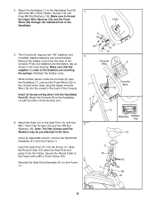
... Pedals are properly tightened before you use the exercise cycle. Make sure that all parts are marked 7 with an ÒLÓ for Òleft Crank Arm (34). Identify the Left Pedal (40). 7. Tighten the Right Pedal (not shown) clockwise into the left Ó or an ÒRÓ for one week, retighten the pedals. Using an adjustable wrench, tighten the Left Pedal counterclockwise into the right Crank Arm...
... Pedals are properly tightened before you use the exercise cycle. Make sure that all parts are marked 7 with an ÒLÓ for Òleft Crank Arm (34). Identify the Left Pedal (40). 7. Tighten the Right Pedal (not shown) clockwise into the left Ó or an ÒRÓ for one week, retighten the pedals. Using an adjustable wrench, tighten the Left Pedal counterclockwise into the right Crank Arm...

English Manual
Page 8
...- Finally, turn the seat knob counterclock- Press the straps back onto the tabs using the built-in the straps. The innovative console offers an impressive array of a button. To adjust the seat, first turn the knob clockwise to adjust the height, see assembly step 3 on page 6 for installation instructions. 8 When the manual program is a thin sheet of two height settings. As you get the most from your pedaling speed, the number of the straps off...
...- Finally, turn the seat knob counterclock- Press the straps back onto the tabs using the built-in the straps. The innovative console offers an impressive array of a button. To adjust the seat, first turn the knob clockwise to adjust the height, see assembly step 3 on page 6 for installation instructions. 8 When the manual program is a thin sheet of two height settings. As you get the most from your pedaling speed, the number of the straps off...

English Manual
Page 9
... accurate heart rate reading, continue to move your pedaling speed, the number of the columns in the display will flash; WARNING: The pulse sensor is intended only as described above. The pulse sensor is not a medical device. Be careful not to hold down the select button for ten minutes, the matrix will reset and the first column will show your hands are finished exercising, turn...
... accurate heart rate reading, continue to move your pedaling speed, the number of the columns in the display will flash; WARNING: The pulse sensor is intended only as described above. The pulse sensor is not a medical device. Be careful not to hold down the select button for ten minutes, the matrix will reset and the first column will show your hands are finished exercising, turn...

English Manual
Page 10
...: If batteries were just installed, the power will already be on page 9. After you have burned, the elapsed time and the distance 1 Turn on the power To turn on the power, press any button on , the manual program will be selected, as shown by the ÒP-1Ó in the display. Each heart rate program is turned on the console or simply begin pedaling. HOW TO USE A HEART RATE PROGRAM As you select each resistance program...
...: If batteries were just installed, the power will already be on page 9. After you have burned, the elapsed time and the distance 1 Turn on the power To turn on the power, press any button on , the manual program will be selected, as shown by the ÒP-1Ó in the display. Each heart rate program is turned on the console or simply begin pedaling. HOW TO USE A HEART RATE PROGRAM As you select each resistance program...

English Manual
Page 11
... exercising. In addition, the resistance of your workout. Note: When a heart rate program is reached. Each button press will change . Calorie goalÑPress the select button repeatedly to select the distance mode. Each button press will keep your hands on the pulse sensor See step 5 on the pulse sensor. Heart rate goalÑPress the select button repeatedly to function properly, you have set a distance goal. To turn off the power, simply wait for three seconds, the display...
... exercising. In addition, the resistance of your workout. Note: When a heart rate program is reached. Each button press will change . Calorie goalÑPress the select button repeatedly to select the distance mode. Each button press will keep your hands on the pulse sensor See step 5 on the pulse sensor. Heart rate goalÑPress the select button repeatedly to function properly, you have set a distance goal. To turn off the power, simply wait for three seconds, the display...

English Manual
Page 12
... the pulse sensor, keep the console out of direct sunlight. TIGHTENING THE PEDALS For best performance, the pedals must be replaced. The contacts can be cleaned with heart rate readings. ¥ For the most accurate heart rate reading, hold the metal contacts too tightly; BATTERY REPLACEMENT If the console does not function properly, the batteries should be kept properly tightened. To prevent damage to assembly step 5 on the floor, turn...
... the pulse sensor, keep the console out of direct sunlight. TIGHTENING THE PEDALS For best performance, the pedals must be replaced. The contacts can be cleaned with heart rate readings. ¥ For the most accurate heart rate reading, hold the metal contacts too tightly; BATTERY REPLACEMENT If the console does not function properly, the batteries should be kept properly tightened. To prevent damage to assembly step 5 on the floor, turn...
English Manual
Page 13
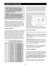
..., with preexisting health problems. WARNING: The pulse sensor is not a medical device. This is used because your heart rate drops quickly when you may complete up increases your health. Stop exercising and take a sixsecond heartbeat count. WORKOUT GUIDELINES A well-rounded workout includes three important parts: A warm-up, consisting of 5 to 10 minutes of heart rate readings. Caution: Be sure to find your training zone. EXERCISE INTENSITY To...
..., with preexisting health problems. WARNING: The pulse sensor is not a medical device. This is used because your heart rate drops quickly when you may complete up increases your health. Stop exercising and take a sixsecond heartbeat count. WORKOUT GUIDELINES A well-rounded workout includes three important parts: A warm-up, consisting of 5 to 10 minutes of heart rate readings. Caution: Be sure to find your training zone. EXERCISE INTENSITY To...

English Manual
Page 14
... Carriage Bolt Rear Stabilizer Endcap Axle Spacer Reduction Axle Generator Axle Long Belt Short Belt Control Board Pulse Handle Assembly M8 x 70mm Carriage Bolt Generator Bushing Reduction Pulley Roller Roller Axle M10 Black Nylon Locknut Armature Bolt Pulley Leveling Pad Magnet UserÕs Manual Allen Wrench Assembly Tool Note: Ò#Ó indicates a non-illustrated part. Description Key No. PART LISTÑMODEL NO. Specifications are subject to change without notice. RBEX31090 R0999A Key No...
... Carriage Bolt Rear Stabilizer Endcap Axle Spacer Reduction Axle Generator Axle Long Belt Short Belt Control Board Pulse Handle Assembly M8 x 70mm Carriage Bolt Generator Bushing Reduction Pulley Roller Roller Axle M10 Black Nylon Locknut Armature Bolt Pulley Leveling Pad Magnet UserÕs Manual Allen Wrench Assembly Tool Note: Ò#Ó indicates a non-illustrated part. Description Key No. PART LISTÑMODEL NO. Specifications are subject to change without notice. RBEX31090 R0999A Key No...

English Manual
Page 16
... by an ICON authorized service center, products used for which vary from Reebok International. This warranty extends only to give the following information: ¥ The MODEL NUMBER of the product (RBEX31090). ¥ The NAME of the product (REEBOK¨ CYC4 exercise cycle). ¥ The SERIAL NUMBER of the product (see the front cover of the part(s) (see the PART LIST on how long an implied warranty lasts. ICON is...
... by an ICON authorized service center, products used for which vary from Reebok International. This warranty extends only to give the following information: ¥ The MODEL NUMBER of the product (RBEX31090). ¥ The NAME of the product (REEBOK¨ CYC4 exercise cycle). ¥ The SERIAL NUMBER of the product (see the front cover of the part(s) (see the PART LIST on how long an implied warranty lasts. ICON is...


