Pyle PDMT25 Support and Manuals
Get Help and Manuals for this Pyle item
Popular Pyle PDMT25 Manual Pages
PDMT25 Manual 1 - Page 1

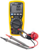
OPERATING INSTRUCTIONS AUTORANGING DIGITAL MULTIMETER
PDMT25
¡ Cã ¡ Fã
Ω
10A
V
10A A
mA
V
www.pyleaudio.com
1
PDMT25 Manual 1 - Page 9

... first turned on 2. The "Auto Range"
display indicator will turn off, The "Manual Range" display indicator will turn on , it automatically goes into AutoRanging. for most measurements. For measurement ...situations requiring that a range be manually selected, perform the following: 1. RANGE button When the meter is generally the best mode...
PDMT25 Manual 1 - Page 10

... test lead banana plug into the (mA) jack.
4. 4.
For current measurements up to 4000uA DC, set the function switch to the mA range and insert the red test lead banana plug into the (uA) ...jack.
3. For current measurements up to 10A DC, set the function switch to the circuit under test. 5.Read the voltage measurement on the LCD display
DC CURRENT ...
PDMT25 Manual 1 - Page 12

...positive side of the circuit. Remove power from the circuit under test, then open up to 10A, set the function switch to the A position and insert the red test lead plug into the 10A jack.... test lead banana plug into the negative (COM) socket.
2. For current measurements up to 10A AC, set the function switch to measure current.
7. Read the current in the display. Apply power to the A ...
PDMT25 Manual 1 - Page 13

...plug into the positive Ω jack. 3. Touch the test probe tips across the circuit or part under test and discharge all capacitors before taking any resistance measurements. Press the MODE button until "Ω...best to disconnect one side of the part under test so the rest of the circuit will indicate the proper decimal point, value and symbol.
13 Set the function switch to the unit under ...
PDMT25 Manual 1 - Page 14

Set the range switch to check. 5. Insert the black lead plug into the COM socket and
the red test lead plug into the positive ))) socket. 3. ...
PDMT25 Manual 1 - Page 15

... the probe polarity by switching probe
position.
If both readings are very small or zero, the
device is open. NOTE: The value indicated in the
4.
B. Set the function switch to test. Insert the black test lead plug into the COM socket
and the red test lead plug into the
socket.
3. Note...
PDMT25 Manual 1 - Page 16

... capacitance position.
2. Note: For very large values of capacitance measurement time can be several minutes before measuring.
1.Set the function switch to discharge the capacitor with some other apparatus.
16 C .Discharging through the chip is disabled in... positive jack.
3.Touch the test probe tips across the part under test before the final reading stabilizes. The LCD displays DIS.
PDMT25 Manual 1 - Page 17

... the correct polarity.
3.Press the MODE button until the reading stabilizes (about 30 seconds).
17 The digital reading will indicate the proper decimal point, symbols (kHz, MHz) and value. Keep the probe touching the part under test. 5. Set the function switch to the circuit under test until "ºF or ºC" appears in the...
PDMT25 Manual 1 - Page 19

... magnitude
of danger from the primary
supply level (overhead or underground utility service).
Low battery indication: A battery "
"symbol is
displayed when the ...IV meters are
designed to protect against transients in fixed-equipment
installations at the distribution level;
CAT III meters are
designed to protect...SPECIFICATIONS
Technical:
Insulation: Class2, Double insulation.
PDMT25 Manual 1 - Page 21

...: 1000V dc or 1000V ac rms.
AC Voltage (Auto-ranging)
Range
Resolution Accuracy
400.0mV 0.1mV
4.000V 1mV
+0.8%of rdg + 3 digits
40.00V 10mV
400.0V 100mV
1000V
1V
+1.2%of rdg + 2 digits
Input Impedance: 7.8MΩ. AC Response: 50 Hz 60Hz
Maximum Input: 1000V dc or 1000V ac rms.
DC Current (Auto...
PDMT25 Manual 1 - Page 22

...Resolution Accuracy
400.0uA 0.1uA
4000uA 1uA
+1.5% of rdg + 5 digits
40.00mA 10uA
400.0mA 100uA
10A
10mA
+3.0% of rdg + 3 digits
Overload Protection: 0.5A / 1000V and 10A / 1000V Fuse. AC...Resolution Accuracy
400.0uA 0.1uA
4000uA
1uA
+1.2% of rdg + 3 digits
40.00mA 10uA
400.0mA 100uA
10A
10mA
+2.5% of rdg + 5 digits
Overload Protection: 0.5A / 1000V and 10A / 1000V Fuse. Maximum...
PDMT25 Manual 1 - Page 23

Resistance [Ω] (Auto-ranging)
Range
Resolution Accuracy
400.0Ω 0.1Ω
+0.8% of rdg + 5 digits
4.000kΩ 1Ω
40.00kΩ 10Ω
+0.8% of rdg + 2 digits
400.0kΩ 100Ω
4.000MΩ 1kΩ
+2.5% of rdg +8digits
40.00MΩ 10kΩ
Input Protection: 1000V dc or 1000V ac rms.
...
PDMT25 Manual 1 - Page 24

... Protection: 1000V dc or 1000V ac rms.
Temperature
Range
Resolution Accuracy
-20oC~+760oC 1 oC -4 oF~+1400 oF 1oF
+3% of rdg +5dgts +3% of rdg + 5
typical/Open
digits
MAX.3V
Open circuit voltage: MAX. 3V dc
24
Sensitivity: >3V RMS while >1MHz ;
Frequency (Auto-ranging)
Range
Resolution Accuracy
4.000kHz 1Hz
40.00kHz 10Hz...
PDMT25 Manual 1 - Page 25

...: 1000V dc or ac rms.
Accessories
Included accessories
Standard Red/Black lead set with test probes
BATTERY and FUSE replacement
WARNING: To avoid electric shock, disconnect the test leads from any source of this manual. 3. Follow instructions for installing battery. See the Battery Installation section of voltage before removing the battery door. 1. When the batteries become...
Pyle PDMT25 Reviews
We have not received any reviews for Pyle yet.