
Installation Manual
Page 1
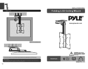
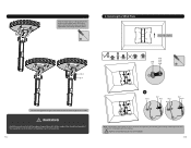
...saving the space, you have any questions. 11 PCMTV25 75x75 100x100 200x100 200x200 CAUTION: DO NOT EXCEED RATED LISTED WEIGHT. SERIOUS INJURY OR PROPERTY DAMAGE MAY OCCUR! 37" MAX 20kg (44lbs) RATED ISSUED: MAR. 2014 7. Adjustment 0°/-90° INSTALLATION MANUAL Folding LCD Ceiling Mount R www.pyleaudio.com Adjust to use... at regular intervals(at least every three months). • Please contact your distributor if you can fold the display by pushing the display ...
...saving the space, you have any questions. 11 PCMTV25 75x75 100x100 200x100 200x200 CAUTION: DO NOT EXCEED RATED LISTED WEIGHT. SERIOUS INJURY OR PROPERTY DAMAGE MAY OCCUR! 37" MAX 20kg (44lbs) RATED ISSUED: MAR. 2014 7. Adjustment 0°/-90° INSTALLATION MANUAL Folding LCD Ceiling Mount R www.pyleaudio.com Adjust to use... at regular intervals(at least every three months). • Please contact your distributor if you can fold the display by pushing the display ...
Installation Manual
Page 2
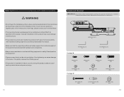
... If you have received all attached hardware and components. • Always use only. If any of the instructions or warnings, please contact your local distributor for indoor use an assistant or mechanical...power. • This product is intended for a replacement. Using this product outdoors could lead to product failure and personal injury. 1 Component Checklist IMPORTANT: Ensure that the supporting surface will safely support the combined weight of the equipment and all parts according to the component checklist prior to installation. NOTE: Read the entire instruction manual...
... If you have received all attached hardware and components. • Always use only. If any of the instructions or warnings, please contact your local distributor for indoor use an assistant or mechanical...power. • This product is intended for a replacement. Using this product outdoors could lead to product failure and personal injury. 1 Component Checklist IMPORTANT: Ensure that the supporting surface will safely support the combined weight of the equipment and all parts according to the component checklist prior to installation. NOTE: Read the entire instruction manual...
Installation Manual
Page 3
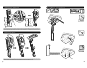
1. Opening the Mount 55mm (2.2"") ø 4.5mm (ø 3/16") 1 mark the exact location of mounting holes. 2 Drill pilot holes Press Open the mount for installing.Press the ceiling plate down,then lift it up till fully open. 3 Tighten the screw leaving a 4mm space to separate the VESA plate from the ceiling mount. 2. For Wooden Ceiling Mounting B Use a proper Allen key to loosen the screws in order to ceiling. Screw the screws into the ceiling W-A 4 Separating the VESA Plate Loosen 3a.
1. Opening the Mount 55mm (2.2"") ø 4.5mm (ø 3/16") 1 mark the exact location of mounting holes. 2 Drill pilot holes Press Open the mount for installing.Press the ceiling plate down,then lift it up till fully open. 3 Tighten the screw leaving a 4mm space to separate the VESA plate from the ceiling mount. 2. For Wooden Ceiling Mounting B Use a proper Allen key to loosen the screws in order to ceiling. Screw the screws into the ceiling W-A 4 Separating the VESA Plate Loosen 3a.
Installation Manual
Page 4
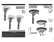
WARNING • Installers are seated in ceiling and move the ceiling plate until the both screws are responsible to provide hardware for other screws and then tighten all ... screws into the ceiling W-A 6 For Solid Brick and Concrete Mounting 60mm (2.4") ø 10mm (ø 3/8") 1 Mark the exact location of mounting holes W-C W-A 2 Drill pilot holes Fix the ceiling plate using the two other types of mounting situations. • Installers must verify that the supporting surface will safely support the combined weight of the equipment and all screws.
WARNING • Installers are seated in ceiling and move the ceiling plate until the both screws are responsible to provide hardware for other screws and then tighten all ... screws into the ceiling W-A 6 For Solid Brick and Concrete Mounting 60mm (2.4") ø 10mm (ø 3/8") 1 Mark the exact location of mounting holes W-C W-A 2 Drill pilot holes Fix the ceiling plate using the two other types of mounting situations. • Installers must verify that the supporting surface will safely support the combined weight of the equipment and all screws.
Installation Manual
Page 5
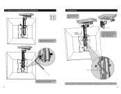
... both holes of ceiling plate to the type of screen. • Screw the VESA plate onto the display. WARNING Installers must verify that the supporting surface will safely support the combined weight of the display W-C W-A Fix the ceiling plate using the two other screws and then tighten all screws. Installing the VESA Plate Top of the equipment and all...
... both holes of ceiling plate to the type of screen. • Screw the VESA plate onto the display. WARNING Installers must verify that the supporting surface will safely support the combined weight of the display W-C W-A Fix the ceiling plate using the two other screws and then tighten all screws. Installing the VESA Plate Top of the equipment and all...
Installation Manual
Page 6
Height adjustable C It is necessary that slightly loosen or tighten adjustment screws to desired height as needed, then tighten screws. 9 10 Loosen screws(but not remove) and adjust the display to adjust tension using a proper Allen key. B B Install the screws to fix the ceiling mount and VESA plate together tightly. 5. Hooking the Display onto the Ceiling Mount 6. Hang the display with the VESA plate onto the ceiling mount. Adjustment Remove the decorative covers for adjusting tension.
Height adjustable C It is necessary that slightly loosen or tighten adjustment screws to desired height as needed, then tighten screws. 9 10 Loosen screws(but not remove) and adjust the display to adjust tension using a proper Allen key. B B Install the screws to fix the ceiling mount and VESA plate together tightly. 5. Hooking the Display onto the Ceiling Mount 6. Hang the display with the VESA plate onto the ceiling mount. Adjustment Remove the decorative covers for adjusting tension.

