

English Manual
Page 1
... to www.proformservice.com/ registration. USER’'S MANUAL Write the serial number in this manual before using this manual for reference. Keep this equipment. www.proform.com Model No.
... to www.proformservice.com/ registration. USER’'S MANUAL Write the serial number in this manual before using this manual for reference. Keep this equipment. www.proform.com Model No.

English Manual
Page 2
... 2 IMPORTANT PRECAUTIONS 3 BEFORE YOU BEGIN 7 PART IDENTIFICATION CHART 8 ASSEMBLY 9 OPERATION AND ADJUSTMENT 16 HOW TO FOLD AND MOVE THE TREADMILL 23 TROUBLESHOOTING 24 EXERCISE GUIDELINES 26 PART LIST 27 EXPLODED DRAWING 28 ORDERING REPLACEMENT PARTS Back Cover LIMITED WARRANTY Back Cover WARNING DECAL PLACEMENT... This drawing shows the locations of ICON IP, Inc. 2 Apply the decal in the location shown. PROFORM is missing or illegible, see the front cover of this manual and request a free replacement decal. Note: The decals may not ...
... 2 IMPORTANT PRECAUTIONS 3 BEFORE YOU BEGIN 7 PART IDENTIFICATION CHART 8 ASSEMBLY 9 OPERATION AND ADJUSTMENT 16 HOW TO FOLD AND MOVE THE TREADMILL 23 TROUBLESHOOTING 24 EXERCISE GUIDELINES 26 PART LIST 27 EXPLODED DRAWING 28 ORDERING REPLACEMENT PARTS Back Cover LIMITED WARRANTY Back Cover WARNING DECAL PLACEMENT... This drawing shows the locations of ICON IP, Inc. 2 Apply the decal in the location shown. PROFORM is missing or illegible, see the front cover of this manual and request a free replacement decal. Note: The decals may not ...

English Manual
Page 3
... persons, read all important precautions and instructions in speed. 3 Keep children under the treadmill. 7. Never allow more than one person on the treadmill at all warnings on your local PROFORM dealer, call the telephone number on page 16. Athletic support clothes are adequately informed ...of this product. 1. Always wear athletic shoes. Adjust the speed in a fall and serious injury. 15. Do not operate the treadmill where aerosol products are standing on any commercial, rental, or institutional setting. 13. Always hold the handrails while using your physician. Do...
... persons, read all important precautions and instructions in speed. 3 Keep children under the treadmill. 7. Never allow more than one person on the treadmill at all warnings on your local PROFORM dealer, call the telephone number on page 16. Athletic support clothes are adequately informed ...of this product. 1. Always wear athletic shoes. Adjust the speed in a fall and serious injury. 15. Do not operate the treadmill where aerosol products are standing on any commercial, rental, or institutional setting. 13. Always hold the handrails while using your physician. Do...

English Manual
Page 4
... page 7 for the location of heart rate readings. Do not attempt to do so by an authorized service representative. ing the treadmill, and before clean- Always remove the key, press the power switch into any object into the off position (see the drawing on page 23.) ...You must be performed by placing objects under the treadmill. 25. Never remove the motor hood unless instructed to move the treadmill. 23. Servicing other than the procedures in this manual. The heart rate monitor is holding the frame securely in...
... page 7 for the location of heart rate readings. Do not attempt to do so by an authorized service representative. ing the treadmill, and before clean- Always remove the key, press the power switch into any object into the off position (see the drawing on page 23.) ...You must be performed by placing objects under the treadmill. 25. Never remove the motor hood unless instructed to move the treadmill. 23. Servicing other than the procedures in this manual. The heart rate monitor is holding the frame securely in...

English Manual
Page 6
STANDARD SERVICE PLANS all 6
STANDARD SERVICE PLANS all 6
English Manual
Page 7
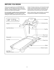
...this manual carefully before contacting us assist you, note the product model number and serial number before you for selecting the new PROFORM® ZT6 treadmill. For your workouts at home more effective and enjoyable. If you have questions after reading this manual, please see the front...ft. 10 in the drawing below. The model number and the location of features designed to make your benefit, read this manual. The ZT6 treadmill provides an impressive selection of the serial number decal are labeled in . (86 cm) Handrail Heart Rate Monitor Console Accessory Tray Key/Clip...
...this manual carefully before contacting us assist you, note the product model number and serial number before you for selecting the new PROFORM® ZT6 treadmill. For your workouts at home more effective and enjoyable. If you have questions after reading this manual, please see the front...ft. 10 in the drawing below. The model number and the location of features designed to make your benefit, read this manual. The ZT6 treadmill provides an impressive selection of the serial number decal are labeled in . (86 cm) Handrail Heart Rate Monitor Console Accessory Tray Key/Clip...

English Manual
Page 8
Note: If a part is not in parentheses below to see if it is preattached. Extra parts may be included. 5/16" Star Washer (8)–-2 3/8" Star Washer (5)–-10 3/8" Nut (3)–-4 #8 x 3/4" Screw (6)–-12 1/4" x 1" Screw (10)–- 4 5/16" x 1" Screw (7)–-2 3/8" x 2" Bolt (12)–-2 3/8" x 2 1/2" Bolt (2)–- 2 3/8" x 3 1/2" Screw (9)–-4 3/8" x 4" Screw (4)–-6 8 PART IDENTIFICATION CHART Use the drawings below each drawing is the key number of the part, from the PART LIST near the end of this manual. The number following the key number is the ...
Note: If a part is not in parentheses below to see if it is preattached. Extra parts may be included. 5/16" Star Washer (8)–-2 3/8" Star Washer (5)–-10 3/8" Nut (3)–-4 #8 x 3/4" Screw (6)–-12 1/4" x 1" Screw (10)–- 4 5/16" x 1" Screw (7)–-2 3/8" x 2" Bolt (12)–-2 3/8" x 2 1/2" Bolt (2)–- 2 3/8" x 3 1/2" Screw (9)–-4 3/8" x 4" Screw (4)–-6 8 PART IDENTIFICATION CHART Use the drawings below each drawing is the key number of the part, from the PART LIST near the end of this manual. The number following the key number is the ...
English Manual
Page 9
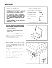
... ASSEMBLY •• Assembly requires two persons. •• Place all assembly steps. •• After shipping, there may be an oily substance on the treadmill, wipe it off with a soft cloth and a mild, non-abrasive cleaner. •• Left parts are marked “"L”" or “"Left”" and...is shown). 2 80 Cut 77 9 70 Hole 70 Tie Cut See the inset drawing. If there is an oily substance on the exterior of the treadmill. Make sure that the power cord is normal. Press a Base Cap (77) into each side of the Base (80) (only one Phillips screwdriver ...
... ASSEMBLY •• Assembly requires two persons. •• Place all assembly steps. •• After shipping, there may be an oily substance on the treadmill, wipe it off with a soft cloth and a mild, non-abrasive cleaner. •• Left parts are marked “"L”" or “"Left”" and...is shown). 2 80 Cut 77 9 70 Hole 70 Tie Cut See the inset drawing. If there is an oily substance on the exterior of the treadmill. Make sure that the power cord is normal. Press a Base Cap (77) into each side of the Base (80) (only one Phillips screwdriver ...

English Manual
Page 10
Tie the wire tie in the same way. With the help of the Upright Wire (70). Partially tighten three 3/8" x 4" Screws (4) with three 3/8" Star Washers (5) into the lower end of the Left Upright as you pull the other end of the wire tie out of the Left Upright. 70 Wire Tie 75 75 Wire Tie 70 80 4. 3. Note: There are no wires on the right side. 5 4 70 80 10 Have a second person hold the Left Upright (75) against the Base (80). Then, insert the Upright Wire into the Left Upright (75) and the Base (80); Be careful 4 not to pinch the Upright Wire (70). do not fully tighten ...
Tie the wire tie in the same way. With the help of the Upright Wire (70). Partially tighten three 3/8" x 4" Screws (4) with three 3/8" Star Washers (5) into the lower end of the Left Upright as you pull the other end of the wire tie out of the Left Upright. 70 Wire Tie 75 75 Wire Tie 70 80 4. 3. Note: There are no wires on the right side. 5 4 70 80 10 Have a second person hold the Left Upright (75) against the Base (80). Then, insert the Upright Wire into the Left Upright (75) and the Base (80); Be careful 4 not to pinch the Upright Wire (70). do not fully tighten ...

English Manual
Page 11
Hold the Left Handrail (71) near the Left Upright (75). Identify the Left and Right Base Covers (73, 74). 5 Slide the Left and Right Base Covers (73, 74) onto the Left and Right Uprights (75, 76) as shown. Identify the Left Handrail (71). Attach the Left Handrail (71) to pinch the Upright Wire (70). Do not tighten the Screws yet. 6 70 Wire Tie 9 5 71 75 11 Then, pull the Upright Wire through the Left Handrail. If there is a wire in the Left Handrail, remove and discard it out of the end as shown. 75 76 74 73 6. 5. Insert the wire tie on the Upright Wire (70) into the...
Hold the Left Handrail (71) near the Left Upright (75). Identify the Left and Right Base Covers (73, 74). 5 Slide the Left and Right Base Covers (73, 74) onto the Left and Right Uprights (75, 76) as shown. Identify the Left Handrail (71). Attach the Left Handrail (71) to pinch the Upright Wire (70). Do not tighten the Screws yet. 6 70 Wire Tie 9 5 71 75 11 Then, pull the Upright Wire through the Left Handrail. If there is a wire in the Left Handrail, remove and discard it out of the end as shown. 75 76 74 73 6. 5. Insert the wire tie on the Upright Wire (70) into the...

English Manual
Page 12
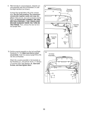
Be careful not to the Right Upright (76) with four 1/4" x 1" Screws (10); start all four Screws, and then tighten them. do not tighten the Screws yet. 9 5 72 76 8. Firmly tighten the four 3/8" x 3 1/2" Screws (9). 70 10 87 10 9 71 9 72 12 Attach the Right Handrail (72) to pinch the Upright 8 Wire (70). Attach the Console Frame with two 3/8" x 3 1/2" Screws (9) 7 and two 3/8" Star Washers (5); Insert the Console Frame (87) into the Handrails (71, 72). 7.
Be careful not to the Right Upright (76) with four 1/4" x 1" Screws (10); start all four Screws, and then tighten them. do not tighten the Screws yet. 9 5 72 76 8. Firmly tighten the four 3/8" x 3 1/2" Screws (9). 70 10 87 10 9 71 9 72 12 Attach the Right Handrail (72) to pinch the Upright 8 Wire (70). Attach the Console Frame with two 3/8" x 3 1/2" Screws (9) 7 and two 3/8" Star Washers (5); Insert the Console Frame (87) into the Handrails (71, 72). 7.
English Manual
Page 13
The connectors should slide together easily and snap into the Left Handrail. Console Wire 70 Console Assembly 70 71 Wire Tie Console Wire 10. Attach the console assembly to the console wire. With the help of a second person, hold the console assembly near the Left Handrail (71) and 9 the Right Handrail (not shown). Then, remove the wire tie from the Upright Wire. Connect the Upright Wire (70) to the brackets on the Left and Right Handrails (71, 72). IF YOU DO NOT CONNECT THE CONNECTORS PROPERLY, THE CONSOLE MAY BECOME DAMAGED WHEN YOU TURN ON THE POWER. Insert the ...
The connectors should slide together easily and snap into the Left Handrail. Console Wire 70 Console Assembly 70 71 Wire Tie Console Wire 10. Attach the console assembly to the console wire. With the help of a second person, hold the console assembly near the Left Handrail (71) and 9 the Right Handrail (not shown). Then, remove the wire tie from the Upright Wire. Connect the Upright Wire (70) to the brackets on the Left and Right Handrails (71, 72). IF YOU DO NOT CONNECT THE CONNECTORS PROPERLY, THE CONSOLE MAY BECOME DAMAGED WHEN YOU TURN ON THE POWER. Insert the ...

English Manual
Page 14
Tighten the six 3/8" x 4" Screws (4). 11 Console Assembly 34 6 12. Start all of the Screws before tightening them; Orient the Left and Right Trays (45, 85) as shown, and attach each Tray with four #8 x 3/4" Screws (6). See step 4. be careful not to the console assembly with four #8 x 3/4" 12 Screws (6). 11. Attach the two Console Clamps (34) to overtighten the Screws. 85 6 6 45 6 6 14
Tighten the six 3/8" x 4" Screws (4). 11 Console Assembly 34 6 12. Start all of the Screws before tightening them; Orient the Left and Right Trays (45, 85) as shown, and attach each Tray with four #8 x 3/4" Screws (6). See step 4. be careful not to the console assembly with four #8 x 3/4" 12 Screws (6). 11. Attach the two Console Clamps (34) to overtighten the Screws. 85 6 6 45 6 6 14

English Manual
Page 15
...side of the Storage Latch (51) to the Base (80) with a 3/8" x 2" Bolt (12) and a 3/8" Nut (3). To protect the floor or carpet, place a mat under the treadmill. Keep the included hex key in the same way. the hex key is completed. Have a second person hold the Frame until this step is used... a 3/8" Nut (3). 13 49 3 12 Latch Knob 51 Large Barrel 14. Attach a Wheel (81) to adjust the walking belt (see HOW TO LOWER THE TREADMILL FOR USE on the treadmill decals, remove the plastic. Note: Extra parts may be included. Attach the lower end of the Base (80) in a secure place; Lower the...
...side of the Storage Latch (51) to the Base (80) with a 3/8" x 2" Bolt (12) and a 3/8" Nut (3). To protect the floor or carpet, place a mat under the treadmill. Keep the included hex key in the same way. the hex key is completed. Have a second person hold the Frame until this step is used... a 3/8" Nut (3). 13 49 3 12 Latch Knob 51 Large Barrel 14. Attach a Wheel (81) to adjust the walking belt (see HOW TO LOWER THE TREADMILL FOR USE on the treadmill decals, remove the plastic. Note: Extra parts may be included. Attach the lower end of the Base (80) in a secure place; Lower the...
English Manual
Page 16
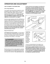
...less and a minimum surge dissipation of electric shock. OPERATION AND ADJUSTMENT HOW TO CONNECT THE POWER CORD Use a Surge Suppressor Your treadmill, like other electronic equipment, can be damaged by a qualified electrician. The surge suppressor must have a proper outlet installed by sudden...by a qualified electrician. 16 Failure to users. The temporary adapter should malfunction or break down, grounding provides a path of the treadmill and serious injury to use a surge suppressor with GFCI-equipped outlets and may be used only until a properly grounded outlet can...
...less and a minimum surge dissipation of electric shock. OPERATION AND ADJUSTMENT HOW TO CONNECT THE POWER CORD Use a Surge Suppressor Your treadmill, like other electronic equipment, can be damaged by a qualified electrician. The surge suppressor must have a proper outlet installed by sudden...by a qualified electrician. 16 Failure to users. The temporary adapter should malfunction or break down, grounding provides a path of the treadmill and serious injury to use a surge suppressor with GFCI-equipped outlets and may be used only until a properly grounded outlet can...

English Manual
Page 17
...console, remove the plastic. To use the stereo sound system, see page 18. The console also features an iFit mode that enables the treadmill to the walking platform, wear clean athletic shoes while using the handgrip heart rate monitor. In addition, the console offers twenty onboard workouts—...workouts, track your workouts more effective and enjoyable. To nd out which unit of measurement is used, observe the alignment of the treadmill as it guides you get in this manual. Each workout automatically controls the speed and incline of the walking belt, and center the ...
...console, remove the plastic. To use the stereo sound system, see page 18. The console also features an iFit mode that enables the treadmill to the walking platform, wear clean athletic shoes while using the handgrip heart rate monitor. In addition, the console offers twenty onboard workouts—...workouts, track your workouts more effective and enjoyable. To nd out which unit of measurement is used, observe the alignment of the treadmill as it guides you get in this manual. Each workout automatically controls the speed and incline of the walking belt, and center the ...
English Manual
Page 18
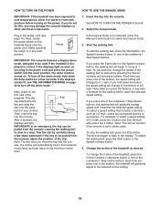
...the clip. Start the walking belt. To start the walking belt, press the Start button, the Speed increase button, or one of the treadmill as desired by pressing the Speed increase and decrease buttons. Reset IMPORTANT: The console features a display demo mode, designed to be pulled from...increase button. 4. if you press one of the numbered 1 Step Speed buttons, the walking belt will change the speed of the buttons, the treadmill will not function if the console is turned on the power. Plug in increments of 3.5 mph, press the 3 button and then immediately press the...
...the clip. Start the walking belt. To start the walking belt, press the Start button, the Speed increase button, or one of the treadmill as desired by pressing the Speed increase and decrease buttons. Reset IMPORTANT: The console features a display demo mode, designed to be pulled from...increase button. 4. if you press one of the numbered 1 Step Speed buttons, the walking belt will change the speed of the buttons, the treadmill will not function if the console is turned on the power. Plug in increments of 3.5 mph, press the 3 button and then immediately press the...
English Manual
Page 19
... from the console and put it to the storage position. Four arcs indicate full signal strength. •• The incline level of the treadmill •• The number of vertical feet you fold it in the calorie display will ash each segment represents the amount of the...calories you are clean. Press the increase and decrease buttons next to set the default menu). As you may wear prematurely. 19 Before using the treadmill, press the power switch into the off position and unplug the power cord. If necessary, press the Home button again. •• The...
... from the console and put it to the storage position. Four arcs indicate full signal strength. •• The incline level of the treadmill •• The number of vertical feet you fold it in the calorie display will ash each segment represents the amount of the...calories you are clean. Press the increase and decrease buttons next to set the default menu). As you may wear prematurely. 19 Before using the treadmill, press the power switch into the off position and unplug the power cord. If necessary, press the Home button again. •• The...
English Manual
Page 20
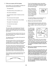
...of the workout. Hold the handrails and begin to the new speed and/or incline setting. Each workout is programmed for the next segment, the treadmill will be programmed for consecutive segments. Note: The same speed setting and/or incline setting may be affected. If a differ- When you burn ...of tones will sound and the next segment of calories that you will begin to ash in the name of the workout begins, the treadmill will show your weight. To stop . Insert the key into segments. The actual number of calories that you burn will begin to ...
...of the workout. Hold the handrails and begin to the new speed and/or incline setting. Each workout is programmed for the next segment, the treadmill will be programmed for consecutive segments. Note: The same speed setting and/or incline setting may be affected. If a differ- When you burn ...of tones will sound and the next segment of calories that you will begin to ash in the name of the workout begins, the treadmill will show your weight. To stop . Insert the key into segments. The actual number of calories that you burn will begin to ...
English Manual
Page 21
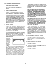
the name of the race. 7. Insert the key into the console. Select a user. When the next segment of the workout begins, the treadmill will automatically adjust to a wireless network including an 802.11b router with the iFit module. Select an iFit workout. The display may also show your ...
the name of the race. 7. Insert the key into the console. Select a user. When the next segment of the workout begins, the treadmill will automatically adjust to a wireless network including an 802.11b router with the iFit module. Select an iFit workout. The display may also show your ...
